


Broyce Control Ltd., Pool Street, Wolverhampton, West Midlands WV2 4HN. England
Tel: +44 (0) 1902 773746 Fax: +44 (0) 1902 420639 Email: sales@broycecontrol.com Web: www.broycecontrol.com
The information provided in this literature is believed to be accurate (subject to change without prior notice); however, use of such information shall be entirely at the user’s own risk
.
P9680[C]-5-A.DOCX
5
5
5
5
2006
I
L1
20.70
A
I>
I
L2
40.00
A
I
L3
27.50
A
I
O
0.00
A
Phase with fault
I
L1
20.70
A
I>>
I
L2
89.00
A
R1 R2
I
L3
27.50
A
I
O
0.00
A
I
L1
0.00
A
I
L2
0.00
A
I
L3
0.00
A
Io>
I
O
1.00
A
I
L1
0.00
A
I
L2
0.00
A
I
L3
0.00
A
Io>>
I
O
8.00
A
R1
Low-set
triggered
High-set
triggered
Relay(s) which
energised on
tripping
Low-set
triggered
High-set
triggered
Relay(s) which
energised on
tripping
Earth fault
current
OVERCURRENT
fault occurs
Low-set I>
triggered
Run IDMT or DT
delay t>
Run DT delay
t>>
High-set
I>>
triggered?
N
Y
TRIP!
Delay
t>
complete?
N
Y
Delay
t>>
complete?
N
Y
START
EARTH FAULT
occurs
Low-set I
o
>
triggered
Run IDMT or DT
delay t
o
>
Run DT delay
t
o
>>
High-set
I
o
>>
triggered?
N
Y
TRIP!
Delay
t
o
>
complete?
N
Y
Delay
t
o
>>
complete?
N
Y
START
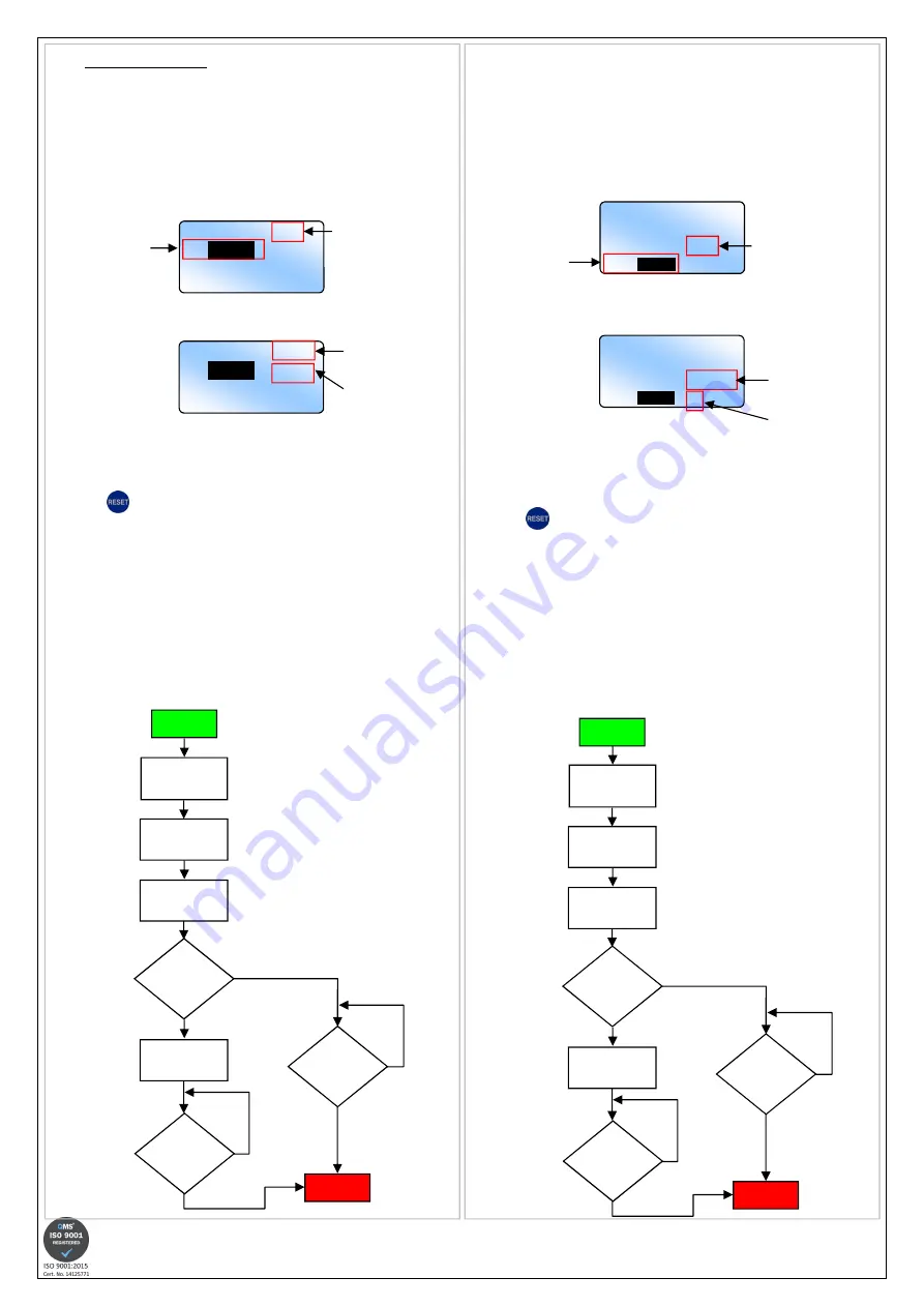
•
TRIPPING MODES
1. OVERCURRENT
•
A fault which develops on a phase will be indicated by an increase in current
reading on the LCD. When the level of current exceeds the Low-set setting,
the phase at fault will be highlighted by the digits flashing.
•
The LCD backlight will flash.
•
Relay 2 will energise if assigned to Overcurrent and set to energise at the start
of the time out period (See Section 3. RELAY 2 SETTING).
•
The characters
“I>”
will display to indicate the Low-set has been triggered.
•
If the current continues to increase above the High-set setting, the
characters
“I>”
will change and display
“I>>”
to indicate the High-set has been
triggered.
•
When the unit finally trips, the digits of the phase at fault will stop flashing and
remain highlighted. This allows the user to see which phase was at fault and
caused the unit to trip.
•
The red “Tripped”
“Tripped”
“Tripped”
“Tripped” LED will also flash.
•
The relays which energised are also displayed on the screen after tripping.
•
Press
to reset and return the unit back to normal operation (assuming
the fault has been cleared). The LCD reverts back to displaying the normal
system currents and the red “Tripped”
“Tripped”
“Tripped”
“Tripped” LED stops flashing.
If either relay is set for Auto resetting, then they would have de-energised after the
fault had cleared. The corresponding relay ident (i.e. R1 and/or R2) on the display
would also disappear. Pressing the “RESET”
“RESET”
“RESET”
“RESET” button will only clear the LCD. If either
relay is set for Manual resetting, then pressing the “RES
“RES
“RES
“RESET”
ET”
ET”
ET” button will de-energise the
relay(s) and clear the LCD.
In the event of an Overcurrent condition, the basic sequence of events is
shown below.
Assuming High-set trip is enabled.
2. EARTH FAULT
•
When an Earth fault occurs causing a flow in current through the Neutral, an
increase in current reading on the LCD will occur. When the level of current
exceeds the Low-set setting, the reading will be highlighted by the digits
flashing.
•
The LCD backlight will flash.
•
Relay 2 will energise if assigned to Earth fault and set to energise at the start of
the time out period (See Section 3. RELAY 2 SETTING).
•
The characters
“Io>”
will display to indicate the Low-set has been triggered.
•
If the current continues to increase above the High-set setting, the
characters
“Io>”
will change and display
“Io>>”
to indicate the High-set has been
triggered.
•
When the unit finally trips, the digits will stop flashing and remain highlighted.
This allows the user to see what caused the unit to trip.
•
The red “Tripped”
“Tripped”
“Tripped”
“Tripped” LED will also flash.
•
The relays which energised are also displayed on the screen after tripping.
•
Press
to reset and return the unit back to normal operation (assuming
the fault has been cleared). The LCD reverts back to displaying the normal
system currents and the red “Tripped”
“Tripped”
“Tripped”
“Tripped” LED stops flashing.
If either relay is set for Auto resetting, then they would have de-energised after the
fault had cleared. The corresponding relay ident (i.e. R1 and/or R2) on the display
would also disappear. Pressing the “RESET”
“RESET”
“RESET”
“RESET” button will only clear the LCD. If either
relay is set for Manual resetting, then pressing the “RESET”
“RESET”
“RESET”
“RESET” button will de-energise the
relay(s) and clear the LCD.
In the event of an Earth fault condition, the basic sequence of events is shown
below.
Assuming High-set trip is enabled.


