


Broyce Control Ltd., Pool Street, Wolverhampton, West Midlands WV2 4HN. England
Tel: +44 (0) 1902 773746 Fax: +44 (0) 1902 420639 Email: sales@broycecontrol.com Web: www.broycecontrol.com
The information provided in this literature is believed to be accurate (subject to change without prior notice); however, use of such information shall be entirely at the user’s own risk
.
P9680[C]-5-A.DOCX
7
7
7
7
2006
Electrical life:
≥
150,000 ops at rated load
Dielectric voltage: 2kV AC (rms) IEC 60947-1
Rated impulse
withstand voltage: 4kV (1.2 / 50
µ
S) IEC 60664
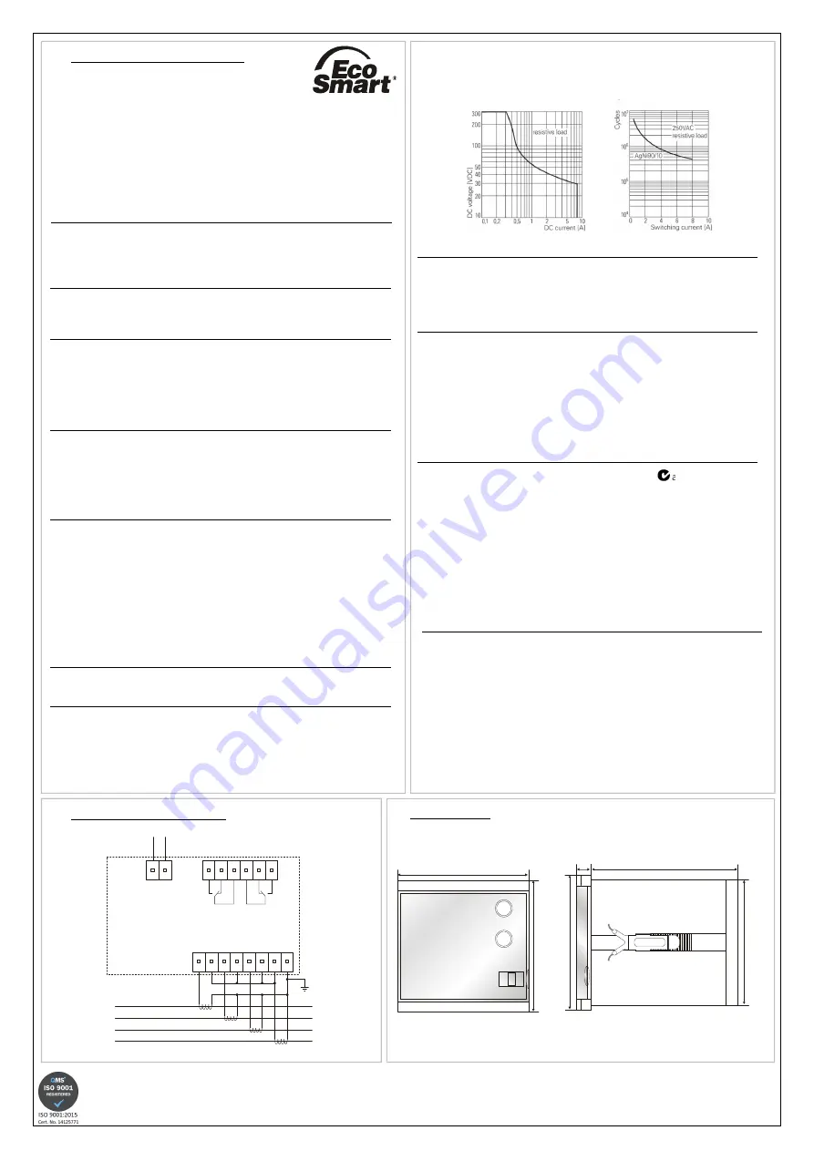
Max. DC Load Breaking Capacity Electrical Endurance
Housing: Flame retardant Lexan
Protection: IP55 / IP20 (rear)
Weight:
≈
600g
Mounting: Panel mounting. Cut-out = 91 x 91mm (
±
0.5mm)
Max. panel thickness: 12mm
Terminal type:
UL94-V0 rated pluggable and re-wireable female
connectors comprising:
2-way (Power supply
1, 2
)
6-way (Relay contacts
3….8
)
8-way (Phase current and neutral inputs
9….16
)
Terminal conductor size: 0.05 - 2.5mm
2
(30 - 12AWG)
Recommended tightening
torque: 4.4in lb (0.5Nm)
Wire stripping length: 0.24 – 0.30in (6 – 7.5mm)
Approvals: Conforms to IEC. CE and and RoHS Compliant.
EMC: Immunity: EN/IEC 61000-6-2
Emissions: EN/IEC 61000-6-4
Generic: IEC 60255-26 (EMC), IEC 255-3, IEC
60255-151
( ) Bold digits in brackets refer to terminal numbers on the rear of the unit.
Options:
The P9600 range also includes individual Overcurrent or Earth fault relays
available with either IDMT or DT characteristics. Please refer to separate data
sheets.
Additional specification details for P9680C
Communication protocol: MODUS RTU
Selectable addresses: 1 – 247
Parity options: Even, Odd, None
Baud rate: 1200 – 115200
Connection method:
Using pluggable, 3.5mm pitch female connector
(supplied with unit)
Recommended wiring type: 2-core + shield (twisted pair, 24AWG)
i.e. Belden type: 9841NH
•
TECHNICAL SPECIFICATION
Aux. Supply voltage Un (
1, 2
): 85 – 265VAC/85 - 370VDC
1
18 – 55VAC/18 – 72VDC*
(Voltage range should be specified at time of
ordering)
Rated frequency: 50/60Hz (AC Supplies)
Isolation: Over voltage cat. III
Rated impulse
withstand voltage:
1
4kV (1.2 / 50
µ
S) IEC 60664
Power consumption: 3W max.
* If connecting a fuse externally, a Time Delay type is recommended with a rating of 0.5A or
higher.
Rated current input In: 5A (directly connected)
Rated frequency: 50/60Hz
Burden: <0.4VA @ In
Overload: 4 x In (continuous)
External CT’s (
9……16
): Class P recommended. (with 5A secondary)
Maximum CT primary
current rating: 6000A
Overcurrent settings:
Low-set trip (I>): 0.50 – 10.00A (10 – 200%)
Low-set time multiplier (k>): 0.05 – 1.00
Low-set definite time (t>): 0.05 – 100s
High-set trip (I>>): 0.5 – 100A (10 – 2000%) or disable
High-set definite time (t>>): 0.05 – 2.5s
Earth fault settings:
Low-set trip (I
o
>): 0.10 – 5.00A (2 – 100%)
Low-set time multiplier (k
o
>): 0.05 – 1.00
Low-set definite time (t
o
>): 0.05 – 100s
High-set trip (I
o
>>): 0.10 – 50.00A (2 – 1000%) or disable
High-set definite time (t
o
>>): 0.05 – 2.5s
Pick up value: +2% of trip setting
Accuracy:
Protection thresholds:
±
5%
Time delay (DT):
±
5% (with a minimum of 50mS)
Time delay (IDMT):
±
5% (with a minimum of 50mS and I > 1.2 x
set-trip)
Actual phase current:
±
1% of rated current In
Actual Earth fault current:
±
1% of rated current In
Display update time: <1 sec.
Repeat accuracy:
±
0.5% @ constant conditions
Ambient temperature: -10 to +60
°
C
Relative humidity: +95%
Output:
(RL1 -
3, 4, 5
): 1 x SPDT relay
(RL2 -
6, 7, 8
): 1 x SPDT relay
Output rating: AC1 250V 8A (2000VA)
AC15 250V 5A (1250VA)
DC1 25V 8A (200W)
•
CONNECTION DIAGRAM
L1
L2
L3
N
A1
A2
RL1
RL2
Aux.
1 2
3
4 5
6 7
9
8
10 11 12 13 14
16
15
I
L1
I
L2
I
L3
I
N
•
DIMENSIONS
Front view Side view
All dimensions are in mm.
96
96
MADE IN U.K.
10
100
89.5
96


