background image


Broyce Control Ltd., Pool Street, Wolverhampton, West Midlands WV2 4HN. England 

Tel: +44 (0) 1902 773746 Fax: +44 (0) 1902 420639 Email: sales@broycecontrol.com Web: www.broycecontrol.com


The information provided in this literature is believed to be accurate (subject to change without prior notice); however, use of such information shall be entirely at the user’s own risk

P9680[C]-5-A.DOCX

  8

8

8

8    

2006 


MODBUS COMMUNICATION OPTION (Model P9680C) 

 
1.

1.

1.

1.


    CONNECTIONS

CONNECTIONS

CONNECTIONS

CONNECTIONS    

 
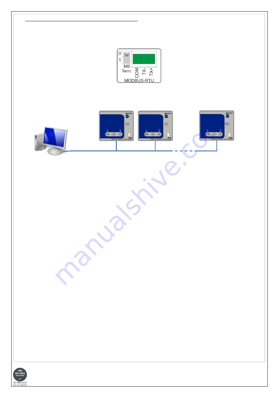
At the rear of the P9680C, a 3-way terminal/connector is provided allowing for connection to the Modbus system. Only 3 terminals are required, COM 
(Common/GND), TX- (or Data -) and TX+ (or Data +). 


Connection for Modbus 

 
A typical example of how the P9680C’s may be arranged is as follows: 


                                      Address 1                         Address 2                                   Address n 


                      Modbus 


                                  Master 
 
The P9680C is provided with a “Modbus termination” switch. It is recommended that for the last unit connected in the system, the switch is set to position “1”. This 
ensures there are no communication issues by minimising the reflections from the end of the bus. 
 
 
2. MODBUS COMMANDS

2. MODBUS COMMANDS

2. MODBUS COMMANDS

2. MODBUS COMMANDS    
 
In summary, utilising the MODBUS features allows for the user to access (and change where relevant) the following: 


Product setup and configuration and define the following: 


External toroid ratio 


Select Network frequency 


Configure Relay 1 and Relay 2 operation 


Configure Overcurrent settings 


Configure Earth Fault settings 


Measurement and Status 


IL1, IL2, IL3, Io live and tripped readings 


Trip history 


Relative time since power up 


Carry out a product Test or Reset operation 

 
The full MODBUS command set is available in a separate document and available on request. 


Summary of Contents for P9680C

Page 1: ...iving early warning before a system actually shuts down Low set and High set thresholds can be programmed for both Overcurrent and Earth fault detection The time current characteristic of the low set...

Page 2: ...occurred continued on next page INSTALLATION BEFORE INSTALLATION ISOLATE THE SUPPLY THIS PRODUCT IS DESIGNED TO CONNECT TO SEVERAL TYPES OF CIRCUITS ENSURE ALL ARE ISOLATED Remove the P9680 P9680 P96...

Page 3: ...fers to Overcurrent and E F refers to Earth fault PROGRAMMING continued Press and hold the button to set the options for Relay 2 Relay 2 Relay 2 Relay 2 as described in the next section 3 RELAY 2 SETT...

Page 4: ...further button presses are made If a trip condition occurs whilst in this mode the screen will automatically change to display the information relating to the current status As described in Section 8...

Page 5: ...been cleared The LCD reverts back to displaying the normal system currents and the red Tripped Tripped Tripped Tripped LED stops flashing If either relay is set for Auto resetting then they would hav...

Page 6: ...0 05 t t t t s s s s 10 1 0 1 0 01 t t t t s s s s Normal Inverse 3 10 Normal Inverse 3 10 Normal Inverse 3 10 Normal Inverse 3 10 NI 3 10 NI 3 10 NI 3 10 NI 3 10 t t t t s s s s k k k k 1 0 0 9 0 8...

Page 7: ...tch female connector supplied with unit Recommended wiring type 2 core shield twisted pair 24AWG i e Belden type 9841NH TECHNICAL SPECIFICATION Aux Supply voltage Un 1 2 85 265VAC 85 370VDC1 18 55VAC...

Page 8: ...is as follows Address 1 Address 2 Address n Modbus Master The P9680C is provided with a Modbus termination switch It is recommended that for the last unit connected in the system the switch is set to...

Reviews: