PARTS TO BE INSTALLED
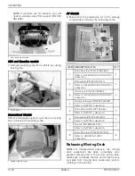
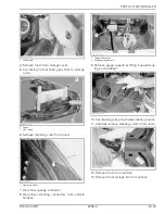
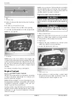
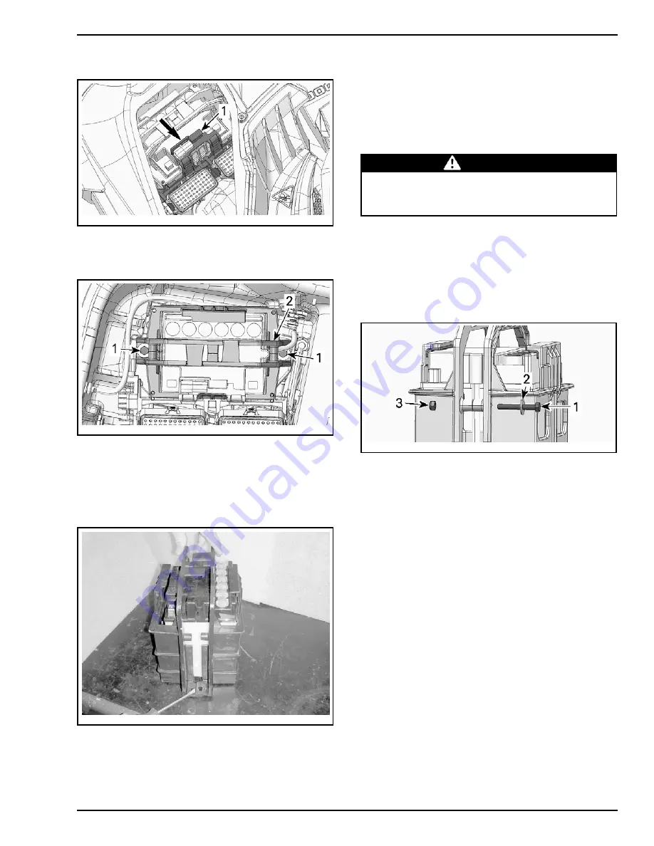
5. Move support aside to make room.
ssi2009-002-008_a
1. Electrical component support
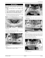
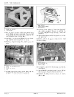
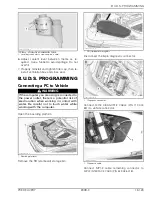
6. Remove and discard screws securing battery
holder to battery holder base (one on each side).
ssi2009-002-009_a
PARTS REMOVED FOR CLARITY
1. Retaining screws
2. Battery holder
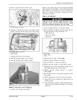
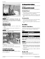
7. Unplug vent hose from battery.
8. Remove battery holder from vehicle.
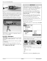
9. Remove battery from battery holder.
sbl2009-004-013_a
Battery Activation and Charging
1. Activate and charge the battery.
Refer to the latest edition of
Sea-Doo BATTERIES
ACTIVATION, CHARGING AND MAINTENANCE
BULLETIN
and to instructions notice attached to
battery for proper activating, charging and main-
tenance procedure.
Battery Installation
WARNING
Always connect battery cables exactly in this
specific order. Connect RED positive cable
first, then BLACK negative ground cable.
1. Install charged battery into battery holder.
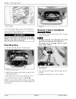
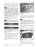
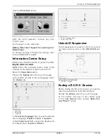
2. Secure battery on battery holder using the fol-
lowing hardware from predelivery kit:
– M6 x 45 bolts
– M6 flat washers
– M6 nuts.
sbl2009-004-050_a
1. M6 x 45 bolt
2. M6 flat washer
3. M6 nut
3. Tighten bolts to 5 N•m (44 lbf•
in
).
4. Position battery holder on vehicle.
5. Plug vent hose on the top of battery.
6. Make sure vent hose is not pinched or bent.
7. Reinstall screws securing battery holder to bat-
tery holder base (one on each side).
8. Tighten battery holder screws to 14 N•m
(124 lbf•
in
).
9. Attach the electrical component support to bat-
tery holder.
10. Insert diagnostic connector into its housing.
11. Apply
DIELECTRIC GREASE (P/N 293 550 004)
on
battery posts.
12. Connect RED (+) battery cable then BLACK (-)
cable using the battery hardware (from prede-
livery kit).
PREDELIVERY
2009-3
7 / 23


