CONTROLS/INSTRUMENTS/EQUIPMENTS
smo2008-001-021_a
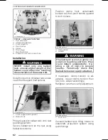
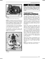
TYPICAL — BALLAST SYSTEM
1. Port side tank
2. Starboard side tank
3. Front supports
4. Rear clamps
5. Valves
6. Drain plugs
7. Overflow holes
8. Propulsion system connections
Installation
WARNING
NEVER install only one ballast
tank, uneven added weight of the
ballast could affect the handling
characteristics of the watercraft.
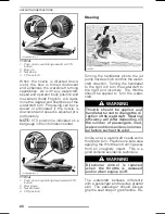
Slide front portion of ballast tank under-
neath front support (half sphere).
smo2008-001-044_a
1. Front support (half sphere)
2. Ballast tank
Properly position ballast tank onto rear
boarding platform.
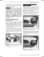
Secure ballast tank at the rear using
ballast tank clamp.
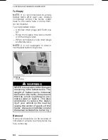
Position
clamp
hook
underneath
bumper rail then push handle upward
to lock in place.
smo2008-001-046_a
1. Clamp hook
2. Handle
WARNING
If ballast tank are not properly se-
cured on boarding platform, they
could detach unexpectedly, cre-
ating a risk of injury to people
nearby.
Periodically check that
ballast tank are properly attached.
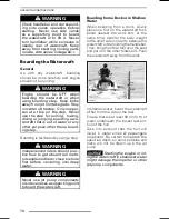
If necessary, clamp tension is ad-
justable, loosen clamp tension then
lock nuts. Adjust accordingly.
Retighten nuts then verify adjustment.
smo2008-001-046_b
1. Lock nuts
Connect ballast tank filling hoses to
watercraft propulsion system using
quick fittings.
62
______________
Summary of Contents for 2009 Sea-Doo GTI Series
Page 9: ...SAFETY INFORMATION ________ SAFETY INFORMATION ________ 7...
Page 39: ...VEHICLE INFORMATION _______________ 37...
Page 83: ...MAINTENANCE INFORMATION _______________ 81...
Page 100: ...STORAGE AND PRESEASON PREPARATION 98 ______________...
Page 101: ...TECHNICAL INFORMATION _______________ 99...
Page 114: ...SPECIFICATIONS 112 ______________...
Page 115: ...TROUBLESHOOTING ______________ 113...
Page 123: ...WARRANTY ______________ 121...
Page 142: ...140 ______________...
Page 144: ...142 ______________...
Page 146: ...144 ______________...


