179
Oiling System
Oiling System Tests
8
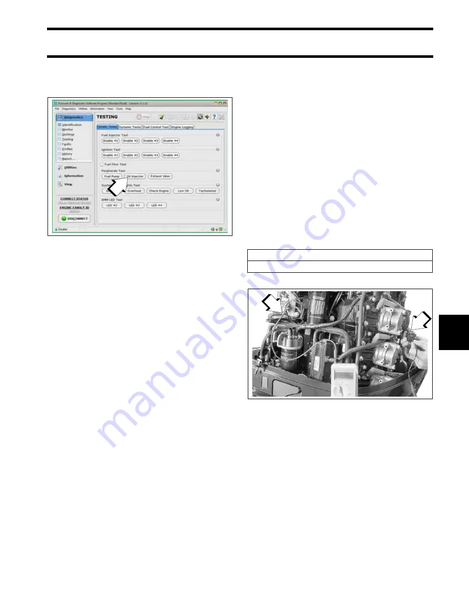
Use the
Oil Injector
test of
Evinrude Diagnostic
software
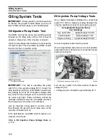
Static Test
screen to activate the oil
pump.
Observe voltage at pin 2.
•
Voltage at pin 2 should drop as the oil pump
cycles.
Check the control signal while the
Oil Injector
test
is running. Set the digital multimeter to the Hertz
(Hz) scale.
•
Meter should read approximately 10 Hz.
Results:
•
If voltage and control signal readings at pin 2
are within range, the
EMM
and wiring are not at
fault.
•
If voltage at pin 2 is not within range, check volt-
age at pin 1 (white/red wire) of oil pump electri-
cal connector.
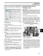
Connect positive meter lead to pin 1 (white/red
wire) of oil injection pump electrical connector.
Observe voltage at pin 1.
•
Voltage at pin 1 should be approximately 30 V.
Start the engine. Observe voltage at pin 1.
•
The voltage at pin 1 should be approximately
55 V.
•
If voltage is not within range, refer to
tion Pump Circuit Resistance Test
•
No voltage reading, refer to
Oil Injection Pump Circuit
Resistance Test
IMPORTANT:
The complete oil injection pump
electrical circuit includes
EMM
alternator output,
the engine wire harness, the injection pump wind-
ing and connectors, and the oil injector control cir-
cuit of the
EMM
. Check continuity of all wiring and
connections.
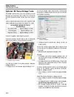
Disconnect the battery cables at the battery.
Disconnect J1-B connector from
EMM
. Use a digi-
tal multimeter with appropriate adapter leads to
measure the resistance between pin 23 (blue) of
the
EMM
J1-B connector and pin 1 (white/red) of
the oil injection pump connector. Calibrate the
meter to the LOW OHMS scale.
•
An infinite reading (
∞
) indicates an open circuit.
Isolate the faulty component. Check continuity
of wiring, connections, or injection pump wind-
ing. Repair faulty wiring or replace faulty pump.
•
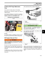
For a higher than expected reading, test resis-
tance of the injection pump. If injection pump
resistance reading is within range, injection
pump winding is good. Isolate faulty compo-
nent. Repair faulty wiring or replace faulty com-
ponent and retest.
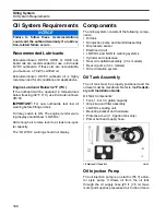
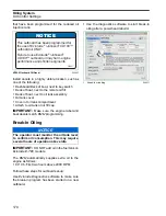
Static Tests Screen
1.
Oil injector test button
008579
1
Oil Injection Pump Circuit Resistance
2 to 3
Ω
1.
EMM
J1-B connector (pin 23)
2.
Oil injection pump connector (pin 1)
004343
2
1
Summary of Contents for EVINRUDE E-TEC BE225HGXABA
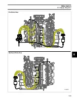
Page 163: ...Oiling System Oil Supply Diagrams 163 8 008208R Port Side View Starboard Side View ...
Page 165: ...Oiling System Oil Supply Diagrams 165 8 008432R Port Side View Starboard Side View ...
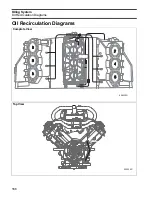
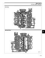
Page 167: ...Oiling System Oil Recirculation Diagrams 167 8 008207R Starboard View Port View ...
Page 251: ...Powerhead Powerhead Views 251 11 Powerhead Views Port Hose Routings 3 3 L models 007153 ...
Page 252: ...252 Powerhead Powerhead Views Starboard Hose Routings 3 3 L models 007154 ...
Page 253: ...Powerhead Powerhead Views 253 11 Port Hose Routings 3 4 L models 008503 ...
Page 254: ...254 Powerhead Powerhead Views Starboard Hose Routings 3 4 L models 008502 ...
Page 255: ...Powerhead Powerhead Views 255 11 Port 3 3 L models 008448 ...
Page 256: ...256 Powerhead Powerhead Views Starboard 3 3 L models 008449 ...
Page 257: ...Powerhead Powerhead Views 257 11 Port 3 4 L models 008441 ...
Page 258: ...258 Powerhead Powerhead Views Starboard 3 4 L models 008442 ...
Page 259: ...Powerhead Powerhead Views 259 11 Front 3 3 L models 008450 ...
Page 260: ...260 Powerhead Powerhead Views Front 3 4 L models 008439 ...
Page 261: ...Powerhead Powerhead Views 261 11 Rear 3 3 L models 007142 ...
Page 262: ...262 Powerhead Powerhead Views Rear 3 4 L models 008440 ...
Page 263: ...Powerhead Powerhead Views 263 11 Top 008438 ...
Page 264: ...264 Powerhead Powerhead Views Starboard ICON models 008504 ...
Page 269: ...Midsection Service Charts 269 12 Muffler 004117R ...
Page 320: ...S 322 ...

