35
Routine Service
Cooling System
2
•
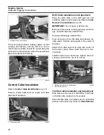
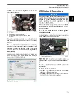
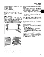
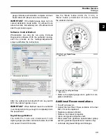
Adjust dial on back of tachometer to required
setting (the outboard should not be running).
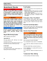
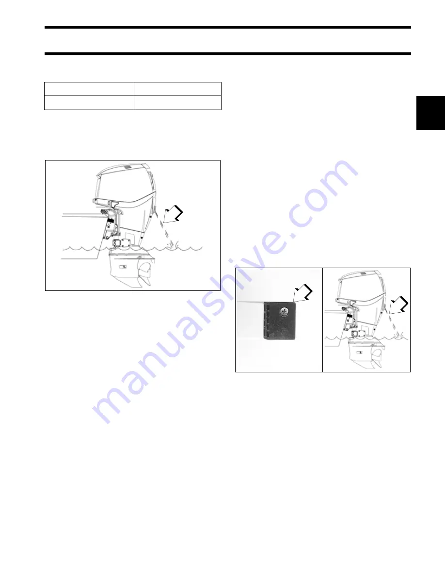
Water Pump Overboard Indicator
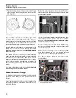
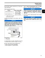
A steady stream of water should flow from the
overboard indicator.
Operating Temperature
An outboard run at idle speed should achieve a
temperature based on the engine’s thermostatic
control. In general, the powerhead temperature
should reach at least 104°F (40°C) after five min-
utes of idling. Check that the powerhead reaches
idle temperature. Refer to
Idle Speed
Make sure the outboard idles within the specified
idle RPM range. If the outboard is run on a flush-
ing device, the idle speed and quality may not be
representative of actual in water use.
Cooling System
Check the condition of cooling system compo-
nents regularly:
•
water intake screens
•
water pump
•
all internal water passages
•
thermostats
•
all external water hoses and fittings
•
vapor separator cooling passages and fittings
•
EMM
cooling passages and fittings
•
overboard water pressure indicator.
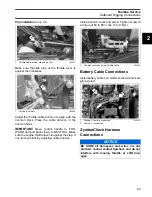
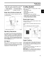
Water Intake Screens
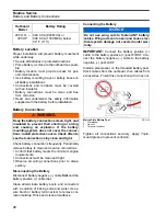
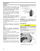
Inspect condition of water intake screens. Clean
or replace as needed.
Confirm function of overboard water pressure indi-
cator.
Clean or replace plug and nozzle as needed.
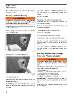
Engine Flushing
Flush the outboard with fresh water following each
use in brackish, salt, or polluted water to minimize
the accumulation of scale and silt deposits in cool-
ing system passages.
The outboard can be flushed on the trailer or at
dockside; running or not running.
IMPORTANT:
The outboard must be located in a
well ventilated area with appropriate ground drain-
age during the flushing procedures.
Outboard Model
Tachometer Setting
200–300 HP
6 Pulse or 12 Pole
1.
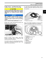
Water pump overboard indicator
008469B
1
1.
Water intake screen
2.
Overboard indicator
DSC02220a
008470A
1
2
Summary of Contents for EVINRUDE E-TEC BE225HGXABA
Page 163: ...Oiling System Oil Supply Diagrams 163 8 008208R Port Side View Starboard Side View ...
Page 165: ...Oiling System Oil Supply Diagrams 165 8 008432R Port Side View Starboard Side View ...
Page 167: ...Oiling System Oil Recirculation Diagrams 167 8 008207R Starboard View Port View ...
Page 251: ...Powerhead Powerhead Views 251 11 Powerhead Views Port Hose Routings 3 3 L models 007153 ...
Page 252: ...252 Powerhead Powerhead Views Starboard Hose Routings 3 3 L models 007154 ...
Page 253: ...Powerhead Powerhead Views 253 11 Port Hose Routings 3 4 L models 008503 ...
Page 254: ...254 Powerhead Powerhead Views Starboard Hose Routings 3 4 L models 008502 ...
Page 255: ...Powerhead Powerhead Views 255 11 Port 3 3 L models 008448 ...
Page 256: ...256 Powerhead Powerhead Views Starboard 3 3 L models 008449 ...
Page 257: ...Powerhead Powerhead Views 257 11 Port 3 4 L models 008441 ...
Page 258: ...258 Powerhead Powerhead Views Starboard 3 4 L models 008442 ...
Page 259: ...Powerhead Powerhead Views 259 11 Front 3 3 L models 008450 ...
Page 260: ...260 Powerhead Powerhead Views Front 3 4 L models 008439 ...
Page 261: ...Powerhead Powerhead Views 261 11 Rear 3 3 L models 007142 ...
Page 262: ...262 Powerhead Powerhead Views Rear 3 4 L models 008440 ...
Page 263: ...Powerhead Powerhead Views 263 11 Top 008438 ...
Page 264: ...264 Powerhead Powerhead Views Starboard ICON models 008504 ...
Page 269: ...Midsection Service Charts 269 12 Muffler 004117R ...
Page 320: ...S 322 ...

