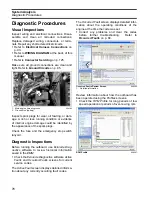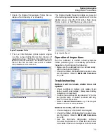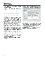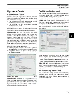
Engine Management Module (EMM)
S.A.F.E. Warning System
66
S.A.F.E.
Warning
System
The
S.A.F.E.
(
Speed Adjusting Failsafe Electron-
ics
) warning system alerts the operator and pro-
tects against engine damage from the following
abnormal conditions:
Activation
When one of these conditions occurs, the
EMM
interrupts fuel injector and ignition operation,
reducing engine speed to 1200 RPM. The warning
horn sounds and an Engine Monitor message dis-
plays. When
S.A.F.E.
is active, the engine will run
normally below 1200 RPM. Above 1200 RPM, the
engine will shake excessively.
Recovery
The engine will operate in
S.A.F.E.
as long as the
fault condition exists. To recover normal operation,
two conditions must be met:
•
Sensor or switch readings must return to normal
limits
•
The throttle setting must return to IDLE
IMPORTANT:
Under some conditions, normal
operation may not be restored, or the lights of the
SystemCheck
gauge may not turn OFF.
•
Some
ICON
fault conditions require the
ICON
system be reset.
•
The
SystemCheck
gauge requires power OFF
to reset
If either of these conditions exist, turn the key
switch OFF, then restart the engine.
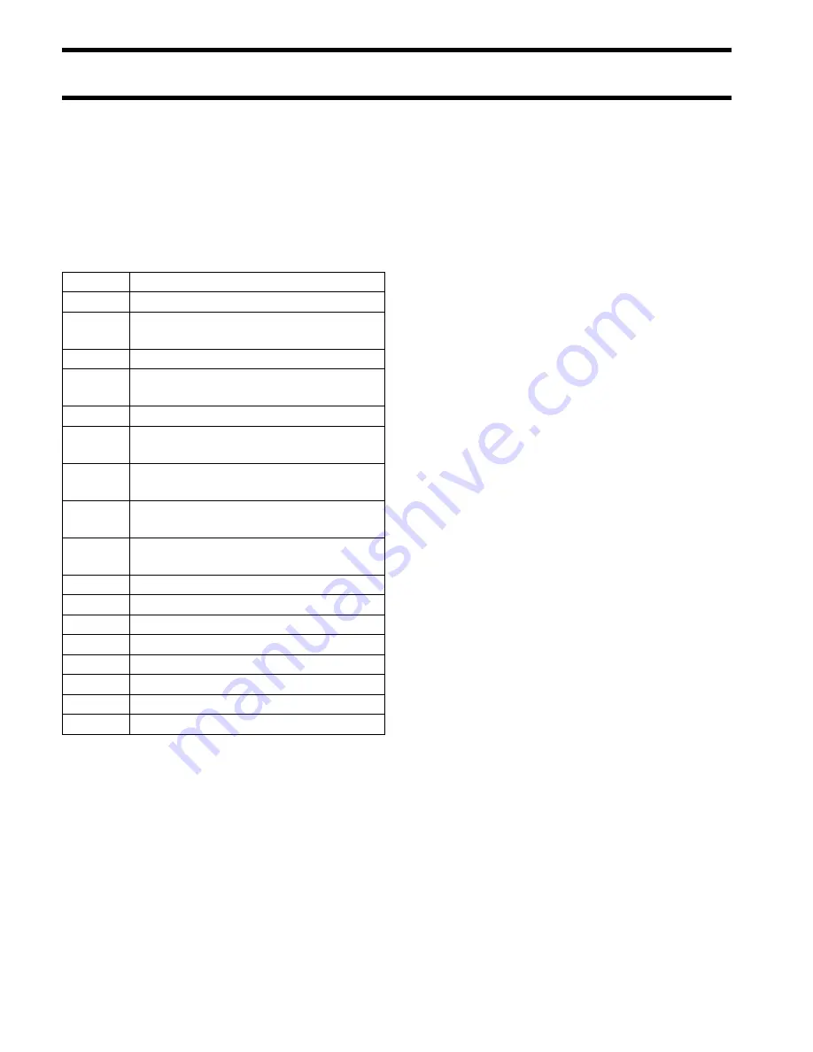
Code 17 Alternator 55 V below expected range
Code 18 Alternator 55 V above expected range
Code 25
EMM
temperature above expected
range
Code 34
Oil injector open circuit
Code 36
Oil injector open circuit (cylinder oil
pump, 3.4 L models only)
Code 38
No oil pressure feedback
Code 40
Cylinder head temperature above
expected range–low speed
Code 43
PORT Cylinder head temperature
above expected range
Code 69 STARBOARD cylinder head tempera-
ture above expected range
Code 70
Cylinder head temperature above
expected range–low speed
Code 107
ICON control communication error
Code 108
ICON system fail-safe mode
Code 109
ICON
control head failure
Code 111
ICON ESM communication error
Code149
ICON throttle actuator sensor fault
Code 150
ICON throttle actuator motion fault
Code 151
ICON shift actuator sensor fault
Code 152
ICON shift actuator motion fault
Summary of Contents for EVINRUDE E-TEC BE225HGXABA
Page 163: ...Oiling System Oil Supply Diagrams 163 8 008208R Port Side View Starboard Side View ...
Page 165: ...Oiling System Oil Supply Diagrams 165 8 008432R Port Side View Starboard Side View ...
Page 167: ...Oiling System Oil Recirculation Diagrams 167 8 008207R Starboard View Port View ...
Page 251: ...Powerhead Powerhead Views 251 11 Powerhead Views Port Hose Routings 3 3 L models 007153 ...
Page 252: ...252 Powerhead Powerhead Views Starboard Hose Routings 3 3 L models 007154 ...
Page 253: ...Powerhead Powerhead Views 253 11 Port Hose Routings 3 4 L models 008503 ...
Page 254: ...254 Powerhead Powerhead Views Starboard Hose Routings 3 4 L models 008502 ...
Page 255: ...Powerhead Powerhead Views 255 11 Port 3 3 L models 008448 ...
Page 256: ...256 Powerhead Powerhead Views Starboard 3 3 L models 008449 ...
Page 257: ...Powerhead Powerhead Views 257 11 Port 3 4 L models 008441 ...
Page 258: ...258 Powerhead Powerhead Views Starboard 3 4 L models 008442 ...
Page 259: ...Powerhead Powerhead Views 259 11 Front 3 3 L models 008450 ...
Page 260: ...260 Powerhead Powerhead Views Front 3 4 L models 008439 ...
Page 261: ...Powerhead Powerhead Views 261 11 Rear 3 3 L models 007142 ...
Page 262: ...262 Powerhead Powerhead Views Rear 3 4 L models 008440 ...
Page 263: ...Powerhead Powerhead Views 263 11 Top 008438 ...
Page 264: ...264 Powerhead Powerhead Views Starboard ICON models 008504 ...
Page 269: ...Midsection Service Charts 269 12 Muffler 004117R ...
Page 320: ...S 322 ...

