149
Fuel System
Fuel Component Servicing
7
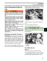
Apply
Nut Lock
to screws and install screws into
throttle body. Tighten screws to a torque of 24 to
36 in. lbs. (2.8 to 4.0 N·m).
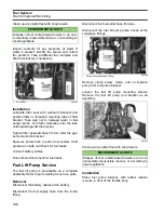
Connect the fuel lift pump pulse hoses to the
crankcase. Secure with tie straps.
Connect the fuel outlet hose to the fuel filter.
Secure with
Oetiker
clamp.
Connect the fuel supply hose to the in-line fitting.
Secure with
Oetiker
clamp.
Squeeze primer bulb to prime fuel system. Hold
pressure on bulb and check for fuel leaks.
Install oil injection pump on bracket with clamp
and screw.
Connect battery cables.
Run outboard and check for fuel leaks.
Vapor Separator Service
Removal
Disconnect the battery cables at the battery.
Relieve fuel system pressure. Refer to
Disconnect circulation pump electrical connector.
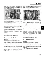
Remove clamp and fuel supply manifold from top
of circulation pump. Remove clamp and vapor
vent hose from separator cover.
Remove clamps and vapor separator cooling
water hoses.
Remove clamps and fuel return manifold and fuel
supply hose from bottom of vapor separator.
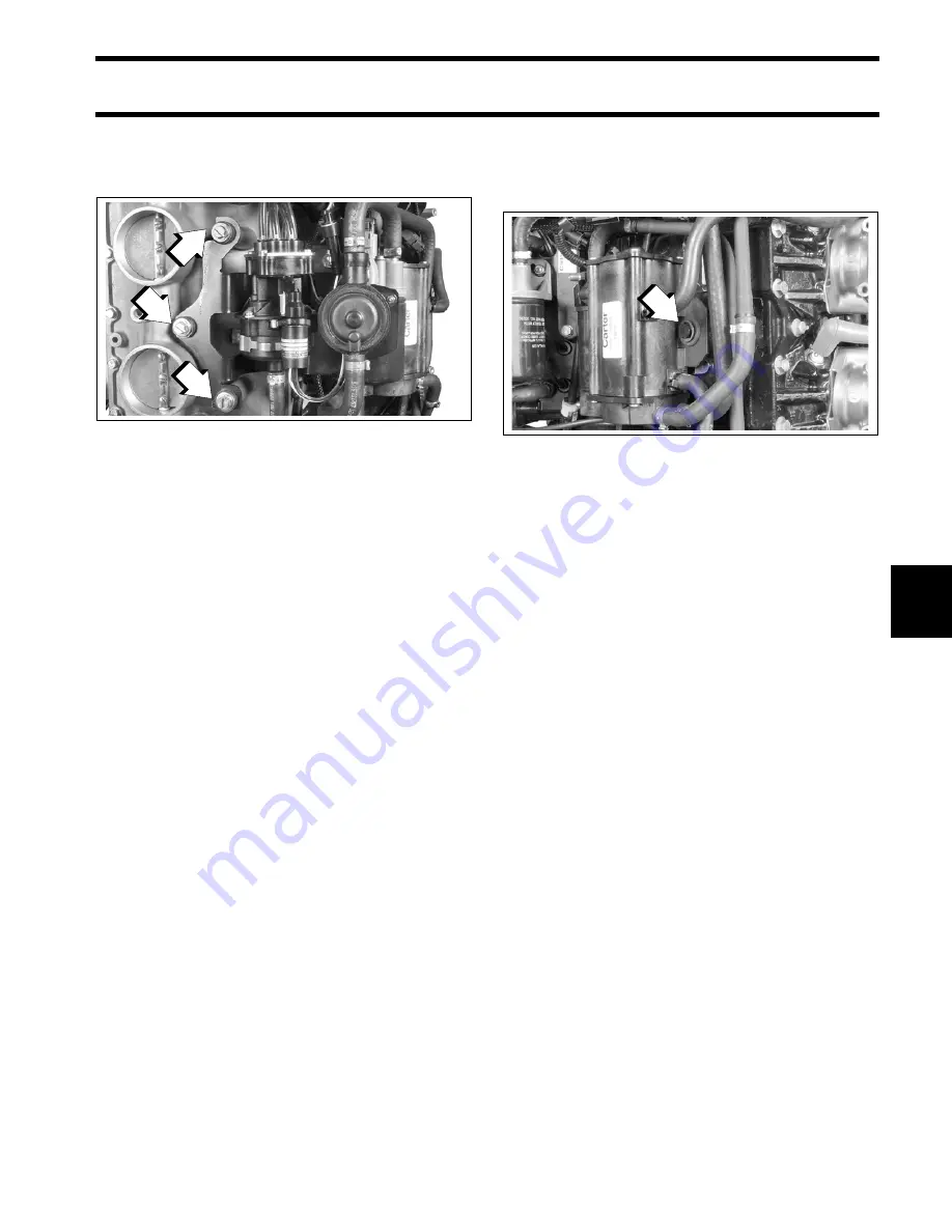
Remove the vapor separator housing retainer clip.
Remove vapor separator/fuel pump from the
mounting stud and slide vapor separator housing
from the grooves of the isolator mounts.
Installation
Slide the vapor separator bracket notches into
grooves of the isolator mounts. Install forward iso-
lator of vapor separator on mounting stud and
secure with retainer clip.
Install all hoses and manifolds in original locations
and secure with appropriate clamps. Squeeze
primer bulb to prime fuel system. Hold pressure
on bulb and observe for fuel leaks.
Connect battery cables.
Run outboard and check for fuel leaks.
Fuel Manifold Service
Removal
Disconnect the battery cables at the battery.
Relieve fuel system pressure. Refer to
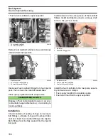
Remove clamps and disconnect the fuel manifolds
as follows:
•
Fuel supply manifold to circulation pump
1.
Screws
004220
1
1
1
1.
Retainer clip
004189
1
Summary of Contents for EVINRUDE E-TEC BE225HGXABA
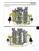
Page 163: ...Oiling System Oil Supply Diagrams 163 8 008208R Port Side View Starboard Side View ...
Page 165: ...Oiling System Oil Supply Diagrams 165 8 008432R Port Side View Starboard Side View ...
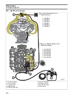
Page 167: ...Oiling System Oil Recirculation Diagrams 167 8 008207R Starboard View Port View ...
Page 251: ...Powerhead Powerhead Views 251 11 Powerhead Views Port Hose Routings 3 3 L models 007153 ...
Page 252: ...252 Powerhead Powerhead Views Starboard Hose Routings 3 3 L models 007154 ...
Page 253: ...Powerhead Powerhead Views 253 11 Port Hose Routings 3 4 L models 008503 ...
Page 254: ...254 Powerhead Powerhead Views Starboard Hose Routings 3 4 L models 008502 ...
Page 255: ...Powerhead Powerhead Views 255 11 Port 3 3 L models 008448 ...
Page 256: ...256 Powerhead Powerhead Views Starboard 3 3 L models 008449 ...
Page 257: ...Powerhead Powerhead Views 257 11 Port 3 4 L models 008441 ...
Page 258: ...258 Powerhead Powerhead Views Starboard 3 4 L models 008442 ...
Page 259: ...Powerhead Powerhead Views 259 11 Front 3 3 L models 008450 ...
Page 260: ...260 Powerhead Powerhead Views Front 3 4 L models 008439 ...
Page 261: ...Powerhead Powerhead Views 261 11 Rear 3 3 L models 007142 ...
Page 262: ...262 Powerhead Powerhead Views Rear 3 4 L models 008440 ...
Page 263: ...Powerhead Powerhead Views 263 11 Top 008438 ...
Page 264: ...264 Powerhead Powerhead Views Starboard ICON models 008504 ...
Page 269: ...Midsection Service Charts 269 12 Muffler 004117R ...
Page 320: ...S 322 ...

