26
Routine Service
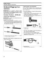
Outboard Rigging Connections
•
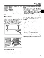
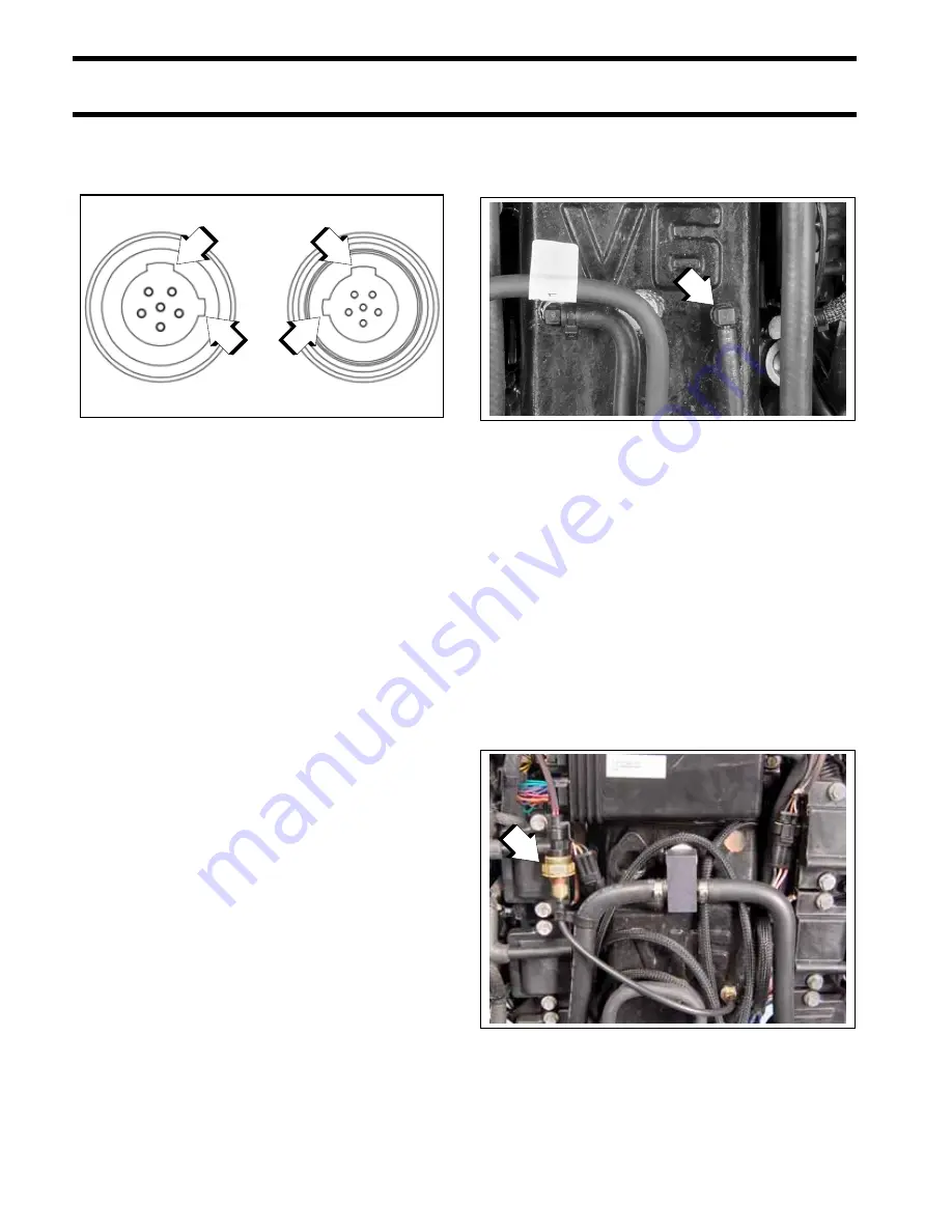
Tighten locking rings of buss connectors finger
tight. Do NOT use locking rings to force connec-
tors together.
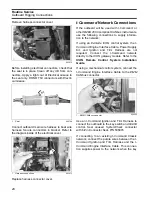
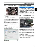
Do not rotate connectors until they align. This
could result in a mismatched connection. It is pos-
sible for each pin to enter a socket even if the tabs
are misaligned. Look at the tabs to ensure con-
nector alignment prior to making the connection.
Engine Monitor information is distributed to an
ICON
or
I-Command
network through the
ICON
gateway module. Refer to the
I-Command
Digital
Network Guide
.
The
ICON
Harness and Relay Kit, P/N 765296,
must be used to provide power to boat accesso-
ries that require switched B+. This kit is used in
place of connecting accessories to the “A” termi-
nal of the key switch. Accessories connected to
the accessory power relay should not exceed 7
amps.
For more information, refer to the
ICON
Remote
Control System Installation Guide
.
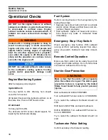
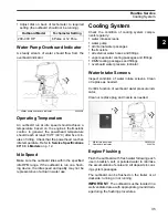
Water Pressure Gauge
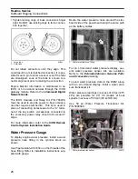
To display engine water pressure, install a water
pressure hose fitting in the cylinder block as
shown.
Use
Pipe Sealant with Teflon
on the threads of the
hose fitting. Refer to installation instructions sup-
plied with gauge.
Route the water pressure hose around the star-
board side of the powerhead along the same path
as the battery cables.
For an
I-Command
water pressure display, sev-
eral water pressure sensor kits are available.
Refer to the
Evinrude/Johnson Genuine Parts
and Accessories
catalog.
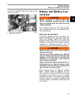
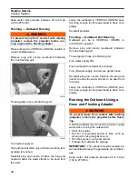
To send water pressure data to the
EMM
, along
with an
I-Command
display, install a water pres-
sure transducer kit.
Water pressure readings in excess of 40 psi (275
kPa) are possible for 90° V6 models at boat
speeds in excess of 50 mph (80 kph/43 kts).
Use 50 psi Water Pressure Transducer Kit,
P/N 5008640.
1.
Large tabs
2.
Small tabs
007883
1
2
1
2
1.
Water pressure hose fitting
005035
1.
Water pressure transducer
008131
1
1
Summary of Contents for EVINRUDE E-TEC BE225HGXABA
Page 163: ...Oiling System Oil Supply Diagrams 163 8 008208R Port Side View Starboard Side View ...
Page 165: ...Oiling System Oil Supply Diagrams 165 8 008432R Port Side View Starboard Side View ...
Page 167: ...Oiling System Oil Recirculation Diagrams 167 8 008207R Starboard View Port View ...
Page 251: ...Powerhead Powerhead Views 251 11 Powerhead Views Port Hose Routings 3 3 L models 007153 ...
Page 252: ...252 Powerhead Powerhead Views Starboard Hose Routings 3 3 L models 007154 ...
Page 253: ...Powerhead Powerhead Views 253 11 Port Hose Routings 3 4 L models 008503 ...
Page 254: ...254 Powerhead Powerhead Views Starboard Hose Routings 3 4 L models 008502 ...
Page 255: ...Powerhead Powerhead Views 255 11 Port 3 3 L models 008448 ...
Page 256: ...256 Powerhead Powerhead Views Starboard 3 3 L models 008449 ...
Page 257: ...Powerhead Powerhead Views 257 11 Port 3 4 L models 008441 ...
Page 258: ...258 Powerhead Powerhead Views Starboard 3 4 L models 008442 ...
Page 259: ...Powerhead Powerhead Views 259 11 Front 3 3 L models 008450 ...
Page 260: ...260 Powerhead Powerhead Views Front 3 4 L models 008439 ...
Page 261: ...Powerhead Powerhead Views 261 11 Rear 3 3 L models 007142 ...
Page 262: ...262 Powerhead Powerhead Views Rear 3 4 L models 008440 ...
Page 263: ...Powerhead Powerhead Views 263 11 Top 008438 ...
Page 264: ...264 Powerhead Powerhead Views Starboard ICON models 008504 ...
Page 269: ...Midsection Service Charts 269 12 Muffler 004117R ...
Page 320: ...S 322 ...

