background image

System Analysis

Ignition Output Tests

84

Ignition Output Tests

Use the 

Evinrude


Diagnostics

 software 

Occurred

Faults

 screen to check for current service codes

before troubleshooting. Correct any problems and
clear the codes FIRST.

Required Ignition Systems

Following is a complete list of circuits required for
ignition output:

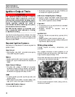
Stop Circuit

Black/yellow wire NOT grounded (emergency
stop switch lanyard in place).

Battery

Battery switched B+ input to power up 

EMM

Battery B+ input to Start Assist Circuit (SAC) of

EMM

Stator Output Voltage

Provides A/C voltage to 

EMM 

J2 connector:

Outboard cranking, typical range is 20-40 VAC
(AC output voltage is related to cranking RPM

)

;

Outboard running approximately 55 VAC.

EMM

Controls ignition grounds, injector grounds, and
ignition timing.

Start Assist Circuit (SAC) converts battery volt-
age (12 V) to 30 V for system circuit (55 V).

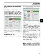
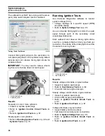
Crankshaft Position Sensor

Provides 

EMM

 with input.

Outboard cranking speed exceeds 75 RPM and
a steady CPS signal is generated.

Alternator Output/System Voltage

System voltage from 

EMM

 (white/red) provides

55 VDC to the oil injection pump, the fuel injec-
tors, and the ignition module of 

EMM

.

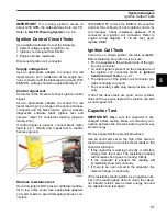
Capacitor

Connected to 55 V circuit (white/red) to stabilize
current on 55 V circuit

Negative terminal of capacitor must be
grounded.

Ignition Coil

Primary circuits are powered by system (55 V)
voltage

EMM

 provides control signal to ignition coil

Output from ignition coil secondary winding and
high tension spark plug wire.

Wiring Inspection

Visually inspect all wiring, connections, and
grounds.

Use a digital ohmmeter to test resistance on all
ground circuits and connections. Ohmmeter read-
ings should be approximately 0.0

Ω

.

Check that all engine wire harness grounds have
continuity to the cylinder/crankcase.

Clean or repair all ground circuits, wiring, and con-
nections as needed.

DANGER

The electrical system presents a serious
shock hazard. Allow outboard to sit for two
minutes after running before handling capaci-
tor or 55 V electrical components. Failure to
handle capacitor properly can result in
uncontrolled electrical discharge and possi-
ble electrical shock to humans. 

DO NOT handle primary or secondary igni-
tion components while outboard is running
or flywheel is turning.

1.

Main engine harness ground

004128

1

Summary of Contents for EVINRUDE E-TEC BE225HGXABA

Page 1: ... a registered trademark of The General Motors Corporation Locquic and Loctite are registered trademarks of The Henkel Group Lubriplate is a registered trademark of Fiske Brothers Refining Company NMEA is a registered trademark of the National Marine Electronics Association Oetiker is a registered trademark of Hans Oetiker AG Maschinen Packard is a registered trademark of Delphi Automotive Systems ...

Page 2: ...em 189 10 Evinrude ICON Remote Control System 201 11 Powerhead 221 12 Midsection 265 13 Trim and Tilt 287 Safety S 321 Index I 345 Trouble Check Chart T 353 Diagrams IMPORTANT For complete outboard rigging and control installation information refer to the Predeliv ery and Installation Guide included with the service manual set All special tools referenced in this manual can be found in the Special...

Page 3: ... of Measurement 6 List of Abbreviations 6 Standard Torque Specifications 7 Product Reference and Illustrations 7 Emission Related Installation Instructions 8 Model Designation 10 Engine Identification 10 Models Covered 11 Service Specifications 90 3 3 L Models 12 Service Specifications 90 3 4 L Models 14 Wire Size Table 16 ...

Page 4: ...including type strength and material Use of substandard parts could result in injury or product malfunction Always wear EYE PROTECTION AND APPRO PRIATE GLOVES when using power tools Unless otherwise specified engine must be OFF when performing this work Always be aware of parts that can move such as flywheels propellers etc Some components may be HOT Always wait for engine to cool down before perf...

Page 5: ...edly Avoid personal injury always support the outboard s weight with a suitable hoist or the tilt support bracket during service To prevent accidental starting while servicing disconnect the battery cables at the battery Twist and remove all spark plug leads The electrical system presents a serious shock hazard DO NOT handle primary or secondary ignition components while outboard is running or fly...

Page 6: ...C American Boat Yacht Council ATDC after top dead center AT air temperature sensor BPS barometric pressure sensor BTDC before top dead center CCA cold cranking amps CFR Code of Federal Regulations CPS crankshaft position sensor EMM Engine Management Module EPA Environmental Protection Agency ICOMIA International Council of Marine Industry Associations ID Inside dimension MCA marine cranking amps M...

Page 7: ...with nauti cal orientation This manual often identifies parts and procedures using these terms Size In Lbs Ft Lbs N m No 6 7 10 0 58 0 83 0 8 1 1 No 8 15 22 1 25 1 83 1 7 2 5 No 10 24 36 2 3 2 7 4 0 No 12 36 48 3 4 4 0 5 4 1 4 in 60 84 5 7 7 9 5 5 16 in 120 144 10 12 13 5 16 5 3 8 in 216 240 18 20 24 5 27 7 16 in 336 384 28 32 38 43 5 M3 15 22 1 25 1 83 1 7 2 5 M4 24 35 2 2 9 2 7 4 0 M5 35 60 2 9 ...

Page 8: ...ne containing greater than ten volume percent ethanol is readily available the US EPA has issued a prohibition against the use of gasoline containing greater than 10 vol ethanol that applies to this engine The use of gasoline containing greater than 10 vol ethanol with this engine may harm the emission control system Manufacturer s Responsibility Beginning with 1999 model year outboards manufactur...

Page 9: ... air pollution from new watercraft marine spark ignition out boards This certification is contingent on certain adjustments being set to factory standards For this reason the factory procedure for servicing the product must be strictly followed and whenever practical returned to the original intent of the design The responsibilities listed above are general and in no way a complete listing of the ...

Page 10: ...t after April 2012 follow the model identification shown above subsequent versions continue through the alphabet as AG AH etc will not use letters from the word INTRODUCES to identify models Refer to Administrative Bulletin 2012 03 A for additional information DESIGN FEATURES C Counter Rotation D Evinrude E TEC E Electric Start w Remote Steering G Graphite Paint H High Output J Jet Drive M Militar...

Page 11: ...B_ White 25 in M2 13 24 542 1 85 1 Standard DE250PXAB_ White 25 in M2 13 24 542 1 85 1 Standard EST 2 E250DCXAB_ White 25 in M2 1 13 24 542 1 85 1 Standard DE250CXAB_ White 25 in M2 1 13 24 542 1 85 1 Standard EST 2 E250DPZAB_ White 30 in M2 13 24 542 1 85 1 Standard DE250PZAB_ White 30 in M2 13 24 542 1 85 1 Standard EST 2 E250DCZAB_ White 30 in M2 1 13 24 542 1 85 1 Standard DE250CZAB_ White 30 ...

Page 12: ...ize dimension to standard bore Top Crankshaft Journal 1 6199 to 1 6204 in 41 15 to 41 16 mm Center Crankshaft Journals 2 1870 to 2 1875 in 55 55 to 55 56 mm Bottom Crankshaft Journal 1 5747 to 1 5752 in 40 0 to 40 01 mm Rod Crankpin 1 4995 to 1 5000 in 38 09 to 38 106 mm Piston Ring End Gap Both 0 022 to 0 028 in 0 57 to 0 72 mm FUEL Fuel Oil Ratio EMM Controlled Starting Enrichment EMM Controlled...

Page 13: ...Features EMM Controlled RPM Limit 6050 Crankshaft Position Sensor Air Gap Fixed Spark Plug Champion QC8WEP 0 028 0 003 in 0 71 mm Refer to Electronic Parts Catalog EPC GEARCASE Gear Ratio M2 Type Gearcase 13 24 542 1 85 1 Lubricant HPF Pro Gearcase Lubricant Capacity M2 Type Gearcase 38 9 fl oz 1150 ml M2 Type Counter Rotation 35 8 fl oz 1060 ml Shift Rod Height 20 in L Models 21 29 32 556 25 mm o...

Page 14: ...o standard bore Top Crankshaft Journal 1 6199 to 1 6204 in 41 15 to 41 16 mm Center Crankshaft Journals 2 1870 to 2 1875 in 55 55 to 55 56 mm Bottom Crankshaft Journal 1 5747 to 1 5752 in 40 0 to 40 01 mm Rod Crankpin 1 4995 to 1 5000 in 38 09 to 38 106 mm Piston Ring End Gap Both 0 022 to 0 028 in 0 57 to 0 72 mm FUEL Fuel Oil Ratio EMM Controlled Starting Enrichment EMM Controlled Preferred Fuel...

Page 15: ...eatures EMM Controlled RPM Limit 6050 Crankshaft Position Sensor Air Gap Fixed Spark Plug Champion QC8WEP 0 028 0 003 in 0 71 mm Refer to Electronic Parts Catalog EPC GEARCASE Gear Ratio M2 Type Gearcase 13 24 542 1 85 1 Lubricant HPF Pro Gearcase Lubricant Capacity M2 Type Gearcase 38 9 fl oz 1150 ml M2 Type Counter Rotation 35 8 fl oz 1060 ml Shift Rod Height 20 in L Models 21 29 32 556 25 mm on...

Page 16: ...3 mm diameter This example has a cross sectional area of 2 08 mm Cross Section 3 Cross Section 3 in mm mm in mm mm 6 0 3335 0 58 14 73 170 3 12 65 0 0808 2 05 3 31 5 0 2646 0 517 13 12 135 1 13 52 0 072 1 83 2 62 4 0 2109 0 46 11 7 107 14 41 0 0641 1 63 2 08 3 0 1665 0 41 10 4 85 15 32 0 0571 1 45 1 65 2 0 1330 0 365 9 26 67 4 16 26 0 0508 1 29 1 31 1 0 1064 0 325 8 25 53 5 17 21 0 0453 1 15 1 04 ...

Page 17: ...nit Adjustment 31 Trim Tab Adjustment 32 Dual Outboard Alignment 32 Operational Checks 34 Cooling System 35 Engine Flushing 35 Running the Outboard Using a Hose and Flushing Adapter 36 Lubrication 38 Steering System 38 Tilt Tube 38 Swivel Bracket and Trailering Bracket 38 Throttle and Shift Linkage 38 Propeller Shaft 39 Gearcase Lubricant 39 Trim and Tilt 40 Spark Plugs 41 Indexing 41 Fuel and Oil...

Page 18: ...trical and ignition wires inspect for wear or chafing Emergency cut off switch es and tether cord check operation EMM access EMM information resolve any service codes Engine Monitor self test and warning horn check Engine to transom mounting hardware re tighten 40 ft lbs Fuel and oil systems inspect and repair leaks 2 2 Emission related component Fuel filters replace Gearcase and water inlet scree...

Page 19: ...ailable in various sizes see PAC Catalog B Biodegradable TNT Fluid P N 763439 Use only in Power Trim Tilt System of 3 cylinder models B Power Trim Tilt Fluid P N 775612 Use only in Power Tilt System of all other models C Triple Guard Grease P N 508298 D Starter Bendix Lube P N 337016 IMPORTANT Use no other products E Hydraulic Fluid P N 770891 Anti Corrosion Spray 6 in 1 Multi Purpose Lubricant WA...

Page 20: ...iple Guard grease Cable Retainer Clip Installation When installing retainer clips on control arm link age pins clips should be locked and must not be bent or deformed For proper installation review the following steps Place washer on pin Position retainer clip with straight section on the bottom and angled section on the top Use long nose pliers to insert straight section of clip into linkage pin ...

Page 21: ...ommet Refer to the following diagram to ensure proper positioning of rigging components in grommet CAUTION To prevent accidental starting while servicing disconnect the battery cables at the battery Disconnect the Crankshaft Position Sensor CPS NOTICE After installation make sure there is enough clearance for all cables to avoid binding or chafing through all engine steering and tilting angles 1 G...

Page 22: ...lip Make sure the remote control gearcase shift link age and shift cable are in NEUTRAL Hold the shift linkage in NEUTRAL Push and pull on the shift cable and observe the cable slack Hold the casing guide in the center of the slack Adjust shift cable trunnion to align with center of the trunnion block Place cable trunnion in trun nion block Install trunnion cover and screw Tighten screw to a torqu...

Page 23: ... If not remove slack by adjusting cable trunnion Install trunnion cover and screw Tighten screw to a torque of 60 to 80 in lbs 7 to 9 N m Battery Cable Connections Install battery cables on starter solenoid and main ground stud SystemCheck Harness Connections 1 Throttle cable retainer clip and washer 003967 1 Throttle lever stop 003968 1 1 1 Trunnion cover and screw throttle cable 005039 1 Positiv...

Page 24: ...an Evinrude ICON control system the I Command Engine Interface Cable Power Supply Kit and Ignition and Trim Harness are not required Connect the I Command network directly to the ICON gateway module Refer to the ICON Remote Control System Installation Guide If using a mechanical control system connect the I Command Engine Interface Cable to the EMM CANbus connector Use an I Command Ignition and Tr...

Page 25: ...e ICON Remote Control System Installation Guide Connect the buss cable from the rear network hub to the outboard s network harness IMPORTANT Do not force connectors or locking rings Properly aligned connectors assemble easi ly Do not use Electrical Grease on ICON buss cable connectors To assemble the connectors Use the large tabs and small tabs to carefully align buss cable connectors Carefully al...

Page 26: ...exceed 7 amps For more information refer to the ICON Remote Control System Installation Guide Water Pressure Gauge To display engine water pressure install a water pressure hose fitting in the cylinder block as shown Use Pipe Sealant with Teflon on the threads of the hose fitting Refer to installation instructions sup plied with gauge Route the water pressure hose around the star board side of the...

Page 27: ...he required battery chargers specified by the battery manufacturer Upon delivery be sure to advise customers that lithium ion batteries and battery chargers MUST be properly maintained and review the battery manufacturer s instructions with the customer 1 Water pressure transducer lead 2 Engine harness connector 004120 2 1 WARNING Battery electrolyte is acidic handle with care If electrolyte conta...

Page 28: ...battery posts and connectors with a solution of baking soda and water Use a wire brush or battery terminal tool to remove cor rosion buildup Rinse and clean all surfaces Connecting the Battery IMPORTANT Connect the battery positive cable to the battery positive post FIRST Con nect the battery negative cable to the battery negative post LAST Install a star washer on the threaded battery post Stack ...

Page 29: ...meter of the hose when installed on the fitting Chose a clamp so that the outside diameter of the hose is approximately in the middle of the clamp ing range of the clamp Clamp Installation A constant stress should be applied to close the ear clamps This method ensures a positive stress on the hose and does not result in excessive com pression or expansion of the band material IMPORTANT Use only Oe...

Page 30: ... the boat s motor well when fully tilted adjust the tilt limit cam to reduce full tilt position Place the outboard in normal operating position 1 000108 1 000090 1 000091 WARNING If the outboard does not clear all boat parts when tilted fully or turned side to side safety related parts could be damaged in the course of such outboard movement Injuries could result from loss of boat control WARNING ...

Page 31: ...at if the possibility for interference and damage exists Trim Sending Unit Adjustment Tilt the outboard and engage the tilt support Temporarily install a thrust rod P N 436541 in the number 3 hole Loosen the sending unit screws to allow the sending unit to pivot Disengage the tilt support Lower the outboard against the thrust rod Observe the trim gauge If the needle does not show center position t...

Page 32: ... left or right when its load is evenly distributed adjust the trim tab as follows With the remote control in NEUTRAL and the engine OFF loosen the trim tab screw If the boat pulled to the right move rear of the trim tab slightly to the right If the boat pulled to the left move rear of the trim tab slightly to the left Tighten the trim tab screw as follows 200 300 HP 35 to 40 ft lbs 47 to 54 N m Te...

Page 33: ...erformance steering and cooling is found A common practice is to set up the outboards par allel or with a small amount of toe out and adjust inward until best results are achieved A typical set up with 2 stroke outboards mounted directly on the transom often runs best with a slight amount of toe in Outboards mounted behind the transom on motor brackets usually require parallel align ment or toe ou...

Page 34: ...rd and shift to FORWARD Turn outboard OFF while control is in FORWARD Try to restart the outboard Outboard should not start Shift back to NEUTRAL and restart outboard Shift to REVERSE Turn outboard OFF while con trol is in REVERSE Try to restart the outboard Outboard should not start Tachometer Pulse Setting Confirm accuracy of tachometer reading DANGER DO NOT run the engine indoors or without ade...

Page 35: ...po nents regularly water intake screens water pump all internal water passages thermostats all external water hoses and fittings vapor separator cooling passages and fittings EMM cooling passages and fittings overboard water pressure indicator Water Intake Screens Inspect condition of water intake screens Clean or replace as needed Confirm function of overboard water pressure indi cator Clean or r...

Page 36: ...r supply ON Flush outboard for at least five minutes Turn off water supply and remove garden hose Reinstall plug and nozzle Position the plug and nozzle to allow the water stream to be seen from the helm Leave the outboard in VERTICAL DOWN posi tion long enough for the powerhead to drain com pletely Running the Outboard Using a Hose and Flushing Adapter A flushing adapter may be used to provide co...

Page 37: ...quirements Be sure to remove waterproof tape from auxiliary water inlets Model Water Flow WOT 200 250 HP 3 3 L 20 to 25 GPM1 75 to 94 LPM 2 250 300 HP 3 4 L 25 to 30 GPM1 94 to 113 LPM 2 NOTICE Temporarily cover the small holes on the front of M2 Type gearcases with waterproof tape to make sure enough water travels to the power head Water can drain from auxiliary inlets resulting in engine overhea...

Page 38: ...ering bracket with Triple Guard grease Throttle and Shift Linkage Disconnect the battery cables at the battery Remove cable trunnion cover Carefully remove throttle and shift cables from trunnion block IMPORTANT DO NOT disturb cable trunnion adjustments Shift remote control into FULL THROT TLE REVERSE position to fully extend the plastic casing guides Apply Triple Guard grease to Pivot and slide a...

Page 39: ...Gearcase Lubricant Draining IMPORTANT Always check the fill level of the gearcase lubricant at the upper plug before remov ing the lower drain fill plug A tie strap can be used to check lubricant level If lubricant level is low refer to Gearcase Leak Test In the Gearcase service manual Remove the lubricant level plug then the lubricant drain fill plug and drain the lube from the gear case into a c...

Page 40: ...mended lubricants Secure the gearcase in a vertical position Remove the lubricant level plug and the lubricant drain fill plug Use Gearcase Filler P N 501882 to slowly fill the gearcase with HPF PRO lubricant through the drain fill hole until it appears at the oil level hole IMPORTANT Filling the gearcase too quickly can cause air pockets and the gearcase may not fill completely Clean plug seal ar...

Page 41: ...park plugs and inspect condition Set spark plug gap on new replacement spark plugs Mark spark plugs for ground electrode orienta tion Apply Electrical Grease to the ribbed portion of the spark plug ceramic and to the opening of the spark plug cover to prevent corrosion Install spark plugs using indexing procedure Indexing Spark plug indexing positions the ground elec trode of the spark plug opposi...

Page 42: ...stricting the incoming fuel or oil supplies Replacement filter elements are available through Evinrude Johnson Genuine Parts Fuel Filter Evinrude E TEC V model outboards are equipped with a water sensing water separating fuel filter Refer to Fuel Component Servicing on p 147 Oil Filters and Oil Reservoir Perform visual inspections to identify oiling system leaks Make certain the oil tank is filled...

Page 43: ... Operation Test Use the Evinrude Diagnostics software Monitor screen to confirm barometric pressure reading and changes in exhaust pressure reading With key ON outboard NOT running make sure the barometric pressure reading reflects actual atmospheric conditions If barometric pressure reading is inaccurate remove exhaust barometric pressure hose from EMM Retest and observe engine Monitor screen If ...

Page 44: ...onents of the out board from galvanic corrosion Outboards are equipped with three sacrificial anodes Visually inspect anodes and metal components below water level Erosion of anodes is normal and indicates the anodes are functioning properly IMPORTANT Anodes that are not eroding may not be properly grounded Anodes and the mount ing screws must be clean and tight for effective corrosion protection ...

Page 45: ...t the outboard s exterior finish from oxidation Clean regularly using clean water and mild detergent soap Touch up damage to painted surfaces promptly Protect moving components with appropriate lubricants Gearcase Removal and Installation Gearcase Removal Remove pin and washer from shift rod lever to release the lower shift rod Note where the index mark on the gearcase aligns with the index number...

Page 46: ...7 to the lower exhaust housing seals inner surfaces Place two new seals on the housing Apply Triple Guard grease to the seals outer surfaces and place the housing on the gear case O L 2 M2 Type Gearcases 1 3 8 16 x 3 5 in screw 2 7 16 14 x 3 5 in screw 006869 1 Gearcase retaining screws 001990 WARNING During service the outboard may drop unex pectedly Avoid personal injury always sup port the outb...

Page 47: ...e treated with a thread locking material Apply Triple Guard grease to threads to ensure that the correct clamp ing force is achieved when tightening If a previ ously installed screw is re used use a wire brush to remove any old thread locking material or corro sion and lubricate threads with Triple Guard grease Install screws and washers and tighten to a torque of 3 8 in screws 26 to 28 ft lbs 35 ...

Page 48: ...utboard will run at idle speed After approximately 15 seconds the System Check lights will go off Move throttle to IDLE position SystemCheck lights will light again Wait another 15 seconds SystemCheck lights will go off At this point advance throttle to FULL in neutral SystemCheck lights will flash indicating that outboard is in winterize mode Outboard will automatically go to fast idle and fog it...

Page 49: ...completely drain the powerhead Digital Gauge Method The ICON Pro 5 inch and I Command 3 5 inch digital gauges provide a winterize feature for 2008 and newer V4 and V6 models Use the Mode button ICON Pro 5 inch or Menu button I Command 3 5 inch to access the winterize feature Refer to the digital gauge user s guide for com plete instructions Additional Recommendations Top off oil reservoir inspect ...

Page 50: ...board Mounting Bolts Check and re tighten outboard mounting bolts to a torque of 40 ft lbs 54 N m Gearcase Lubricant Check the lubricant level Inspect gearcase for leaks If leak is apparent pressure and vacuum test gearcase Repair gearcase as needed Battery s Replace batteries that cannot be charged Power Trim and Tilt Remove filler cap and check fluid level Inspect the power trim and tilt unit fo...

Page 51: ...upply hose and oil return hose from outboard Drain and clean all oil hoses fil ters and oil tank assemblies Refill fuel tank with fresh fuel and oil tank with rec ommended oil Prime oil system and fuel system Refer to Fuel System Priming on p 142 and Oil Supply Prim ing on p 175 Make sure all oil injection hoses are clean and filled with oil Make sure high pressure fuel system does not contain wat...

Page 52: ...6360 410 349729 331 352335 346 351685 316 349759 301 346153 256 346152 241 352703 226 353516 I D P N 1 2 3 8 1 4 1 8 3 4 1 1 1 4 1 1 2 1 3 4 2 2 1 4 695 352868 66 3 to 69 5 mm 2 61 to 2 73 in 845 358657 81 3 to 84 5 mm 3 20 to 3 32 in 605 351159 57 3 to 60 5 mm 2 25 to 2 38 in 995 356019 96 3 to 99 5 mm 3 79 to 3 92 in I D P N 50 55 60 008458 Rev E Clamping Range Hose Diameter Extra Large Clamps C...

Page 53: ...r Service Table of Contents Upper Cover Service 54 Latch Hook Installation 54 Upper Cover Cap Replacement 54 Lower Cover Service 55 Lower Cover Removal 55 Lower Cover Installation 55 Latch Handle Installation 56 Trim Switch Installation 56 ...

Page 54: ...sition on bracket Apply Ultra Lock to screw threads Tighten screws to a torque of 60 to 84 in lbs 7 to 9 5 N m Upper Cover Cap Replacement Place new upper cap into position Tighten self tapping screws to a torque of 24 to 36 in lbs 2 7 to 4 N m 006962 006963 006815 1 Upper cap screws 006964 1 1 1 1 1 1 1 1 ...

Page 55: ...htly and disconnect trim tilt switch connector Then remove port and starboard covers Lower Cover Installation Install the lower engine covers and tighten all screws to a torque of 24 to 36 in lbs 3 to 4 N m Connect trim tilt switch connector 1 Lower cover screws 005242 005246 1 1 1 1 1 1 1 1 1 1 Lower cover screws 005242 005246 1 1 1 1 1 1 1 1 1 ...

Page 56: ...ck to screw threads Place spring washer and hook into position and tighten screw to a torque of 180 in lbs 20 N m Trim Switch Installation Place switch into position through cover Install nut on switch Tighten nut to a torque of 10 to 16 in lbs 1 to 2 N m Install electrical connector Refer to Connector Servicing on p 125 1 Triple Guard grease 006827 006821 006746 1 006747 006748 ...

Page 57: ...tral Shift Interrupt Switch 61 Internal EMM Functions 62 Start Assist Circuit SAC 62 ROM Verification 62 Idle Controller 62 RPM Limiter 62 Neutral RPM Limiter 62 Engine Monitor and Warning Systems 62 Fault Code Creation and Storage 62 Engine Monitor System 63 S A F E Warning System 64 Shutdown Mode 65 Diagnostic Software Functions 65 Communication 65 Static Information 66 Dynamic Information 66 Oc...

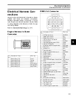
Page 58: ...ours Oiling ratios Shift interrupt function Anti knock compensation EMM Connections IMPORTANT EMM connections and wiring must be clean and tight Improper electrical con nections can damage the EMM DO NOT run the outboard with loose or disconnected wiring Make sure EMM connections are clean and tight Engine wire harness to EMM connectors J1 A J1 B J2 Stator to EMM connections one 6 pin AMP and J2 c...

Page 59: ...ensor circuit fault is detected and the EMM 55 V Circuit Sensor Monitors the EMM s 55 V alternator circuit If system voltage exceeds 57 volts the EMM If system voltage is less than 45 V between 500 and 1000 RPM or is less than 52 V above 1000 RPM the EMM 12 V Circuit Sensor Monitors the EMM s 12 V alternator circuit If battery voltage exceeds 15 5 volts the EMM If battery voltage is less than 12 V...

Page 60: ...Exhaust Pressure Sensor The exhaust pressure sensor monitors exhaust pressure during all running conditions to compen sate for engine loads If the sensor reads less than 85 in water or greater than 85 in water or the sensor or circuit fails the EMM If exhaust pressure is less than 40 in water the EMM If exhaust pressure is greater than 80 in water the EMM Stores service code 78 EMM LED 3 OFF Crank...

Page 61: ...3 seconds the EMM If cylinder head temperature exceeds 248 F 120 C for 3 seconds the EMM The outboard will not restart until the engine tem perature returns to normal Refer to Shutdown Mode on p 67 If sensor values are less than 13 F 25 C or greater than 329 F 165 C the EMM If sensor values are below 4 F 20 C the EMM If cylinder head does not reach operating tem perature 122 F 50 C below 1000 RPM ...

Page 62: ...M If the outboard is started the code is saved If the key ON voltage is greater than 0 78 V when the engine is started speed is limited to idle If code 11 is present as both a Active Fault and a Occurred Fault refer to Control Cable Installa tion on p 22 If the TPS or TPS circuit fails less than 0 14 volts or greater than 4 92 volts the EMM IMPORTANT When a TPS circuit fault has been detected the ...

Page 63: ...d cylinder If knock continues the EMM If the sensor circuit is OPEN the EMM Neutral Shift Interrupt Switch A switch mounted on the powerhead signals the EMM when the shift linkage is moved from FOR WARD or REVERSE into NEUTRAL A cam on the powerhead shift arm closes the switch in NEUTRAL completing a ground circuit to the EMM This signal is used to control Neutral RPM limit Shift Interrupt functio...

Page 64: ...ings are altered to maintain a specific RPM when engine is cold or warm The controller is inactive when TPS is advanced from idle position RPM Limiter This feature of EMM programming prevents engine damage due to excessive RPM At 6250 RPM fuel and ignition to the cylinders is shut off Normal operation resumes when engine RPM returns to the specified range Neutral RPM Limiter This feature prevents ...

Page 65: ... this manual for a complete list of all fault codes System Self Test During engine start up pause with the key switch in the ON position The horn self tests by sound ing a half second beep SystemCheck gauges self test by turning the indicator lights on simulta neously then off in sequence Note The warning horn does NOT sound in an I Command installation Service Mode SystemCheck goes into a service...

Page 66: ...SystemCheck gauge may not turn OFF Some ICON fault conditions require the ICON system be reset The SystemCheck gauge requires power OFF to reset If either of these conditions exist turn the key switch OFF then restart the engine Code 17 Alternator 55 V below expected range Code 18 Alternator 55 V above expected range Code 25 EMM temperature above expected range Code 34 Oil injector open circuit Co...

Page 67: ... Functions The EMM saves valuable information about the outboard and its running history This information can be used for troubleshooting for checking parts information and for making adjustments to the system Use Evinrude Diagnostics software version 5 1 or higher and a laptop computer to access program information IMPORTANT For software help refer to the Help menu in the software Communication L...

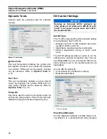
Page 68: ...en must match the actual cylinder placement for each injector Dynamic Information Dynamic information is viewed while the outboard is running Changes in data such as voltages or temperatures are shown as they happen Occurred Faults Service codes are saved if an abnormal condition occurs while the outboard is running The Occurred Faults screen of the diagnostics software shows the code number the n...

Page 69: ... circuit Refer to Static Ignition Test on p 85 Fuel Test Use the diagnostics software to test each fuel injector circuit Refer to Fuel Injector Static Test on p 82 Oil Injector Use the diagnostics software to test the oil injec tion pump circuit Refer to Oiling System Tests on p 178 Fuel Pump Use the diagnostics software to test the fuel pump circuit Refer to Fuel Pump Static Test on p 82 Overheat...

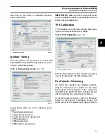
Page 70: ...Settings Set Oil Type The TC W3 oil type setting is the standard setting for all outboards Set TC W3 for Operation with all TC W3 outboard oils includ ing XD30 XD50 or XD100 Applications requiring maximum lubrication Extreme applications racing or harsh condi tions The XD100 setting provides an option to run the outboard at a reduced oil injection rate This set ting REQUIRES the use of Evinrude XD...

Page 71: ...ing temperature before making adjustments TPS Calibration TPS Calibration synchronizes throttle plate open ing with throttle position sensor voltage Refer to TPS Calibration on p 116 Perform TPS Calibration after replacing or adjust ing any throttle body or throttle linkage parts Fuel Injector Servicing All E TEC fuel injectors use software program ming to compensate for variations in fuel flow Ea...

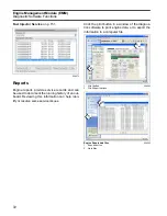
Page 72: ... the running history of an out board Reviewing this information can help iden tify or resolve some service issues Click the print button in a window of the diagnos tics software to print engine data or to export the information to a computer file 008573 1 Print button 2 Print Export options 008592 Engine Report data files 1 Exports button 2 Data files 008593 2 1 2 1 ...

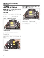
Page 73: ...rap Tool P N 586551 Install tool between engine and boat harness key stop switch connectors as instructed by update program EMM Transfer EMM Transfer is used to save engine history data when the EMM must be replaced Select EMM Data Transfer from the Utilities menu Select Perform Transfer From Memory and follow the instructions provided with the program IMPORTANT Whenever the EMM is replaced EMM ti...

Page 74: ...rews Lift EMM away and to the starboard side Installation Align slots in starboard side of EMM case with iso lator mounts on cylinder block Slide EMM into position Install two EMM retaining screws Tighten screws 12 to 16 in lbs 1 5 to 2 N m Install J1 A J1 B and J2 connectors Install exhaust pressure hose and cooling hoses Secure with tie straps 1 EMM mounting screws 006967 1 EMM mounting slots 2 ...

Page 75: ...ctive Amp Meter Test 77 EMM LED Indicators 78 Key ON 78 Starting 78 Running 78 Fuel Delivery Tests 80 Fuel Pump Static Test 80 Fuel Injector Static Test 80 Running Fuel System Tests 81 Ignition Output Tests 82 Required Ignition Systems 82 Wiring Inspection 82 Crankshaft Position Sensor CPS Test 83 System Voltage Test 83 Static Ignition Test 83 Running Ignition Tests 84 Ignition Control Circuit Tes...

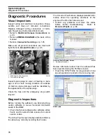
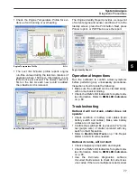
Page 76: ... lanyard Diagnostic Inspections Before running the outboard use Evinrude Diag nostics software to review historical information saved in the EMM Check the Evinrude Diagnostics software Active Faults and Occurred Faults screens for current service codes The Active Fault screen displays detailed informa tion about any currently occurring fault codes The Occurred Fault screen displays detailed infor ...

Page 77: ...sure the outboard can be cranked easily with no mechanical binding Check the EMM LED Indicators for system sta tus information Refer to EMM LED Indicators on p 80 Troubleshooting Outboard will not crank starter does not operate Check condition of battery and cables main battery switch and cables Make sure battery cables are not reversed Confirm that switched B is present at A termi nal purple wire...

Page 78: ...Use the diagnostics software Dynamic Tests to isolate a faulty cylinder See Dynamic Tests on p 79 Use an inductive timing light to check ignition and fuel injector circuits Refer to Running Igni tion Tests on p 86 and Running Fuel System Tests on p 83 Use the diagnostics software Fuel Control Adjustment test to help identify a cylinder that may be too rich or too lean Refer to Fuel Con trol Adjust...

Page 79: ...ts IMPORTANT DO NOT misinterpret tests run at IDLE The idle speed controller in the EMM com pensates to maintain a constant IDLE speed The Dynamic Tests screen includes a function to tem porarily disable the idle controller Fuel Control Adjustment Use this test is to help identify a cylinder that may be too rich or too lean This feature should not be used by itself to identify a faulty injector Ev...

Page 80: ...ault Code 12 TPS circuit fault Code 13 TPS below expected range Code 14 TPS above expected range Code 23 EMM temp sensor circuit fault Code 24 EMM temp below expected range Code 37 Water in fuel Code 41 Port temp sensor circuit fault Code 42 Port temp below expected range Code 47 AT sensor circuit fault Code 48 AT sensor below expected range Code 49 AT sensor above expected range Code 58 Operating...

Page 81: ...knock Code 6 No 6 cylinder excessive knock Code 7 PORT Knock sensor circuit fault Code 8 STBD Knock sensor circuit fault Code 12 TPS circuit fault Code 13 TPS below expected range Code 14 TPS above expected range Code 16 CPS intermittent loss of sync Code 23 EMM temp sensor circuit fault Code 24 EMM temp below expected range Code 28 Shift switch malfunction Code 37 Water in fuel Code 41 PORT temp ...

Page 82: ...or Static Test Use the Evinrude Diagnostics software Fuel Injec tor Static Test to activate each fuel injector Listen for an audible click from each injector when it is actuated If the injector activates the EMM and injector circuits are not at fault IMPORTANT This test is operating the injectors with 30 V on the system voltage 55 V circuit The start assist circuit SAC of the EMM converts bat tery...

Page 83: ... light pickup and the oper ation of the timing light Results No light activation on any injector wires outboard cranks and starter turns flywheel Check stator input to EMM CPS operation and all grounds and wiring connections Eliminate all other possibilities to isolate a faulty EMM Irregular or no light activation on some injector wires Test the resistance of individual injector circuits between t...

Page 84: ...ge from EMM white red provides 55 VDC to the oil injection pump the fuel injec tors and the ignition module of EMM Capacitor Connected to 55 V circuit white red to stabilize current on 55 V circuit Negative terminal of capacitor must be grounded Ignition Coil Primary circuits are powered by system 55 V voltage EMM provides control signal to ignition coil Output from ignition coil secondary winding...

Page 85: ...than 30 V 2 check 12 V power to EMM Repair connection or wiring Possible fault in EMM SAC circuit RUNNING 55 V 2 system voltage is GOOD RUNNING less than 55 V 2 check stator output to EMM Repair connection or wiring Possible faulty stator or EMM Refer to Stator Tests on p 98 IMPORTANT The EMM must be ON for voltage to be present on the system voltage 55 V circuit Power is normally supplied to the ...

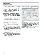
Page 86: ... p 85 Use an inductive timing light to monitor the spark signal through each of the secondary circuit spark plug lead wires Start outboard and observe timing light strobe Look for a consistent flash and only one flash per revolution The strobe of the timing light should be the same for each cylinder Results Steady voltage and strobe engine misfires Inspect or replace spark plugs Refer to Fuel Deli...

Page 87: ...t orange Check resistance between J1 B connector and ignition coil connector Refer to engine wiring diagram If circuits test good replace EMM Ignition Coil Tests There are no simple ignition coil tests available Before replacing an ignition coil be sure 55 V is supplied to the white red wire of the igni tion coil connector A control signal is present on the orange wire of the ignition coil connect...

Page 88: ...System Analysis Notes 88 Notes Technician s Notes Related Documents Bulletins Instruction Sheets Other ...

Page 89: ...100 55 V Alternator Circuit 101 Electric Start Circuit 102 Electric Start Tests 104 Remote Control Switch Tests 106 Tilt Trim Relay Test 108 SystemCheck Circuit Tests 109 Tachometer Circuit Tests 111 Flywheel and Stator Servicing 112 Flywheel Removal 112 Stator Service 112 Flywheel Installation 112 Ignition Coil Servicing 114 Ignition Coil Removal 114 Ignition Coil Bracket Removal 114 Ignition Coi...

Page 90: ... X see Service Manual Y Thermal Joint Compound F 30 42 In lbs 3 5 4 7 N m T 60 84 In lbs 7 9 5 N m X J 50 70 In lbs 5 6 8 N m F 30 42 In lbs 3 5 4 7 N m F 30 42 In lbs 3 5 4 7 N m 60 84 In lbs 7 9 5 N m X 15 30 Ft lbs 20 41 N m 10 16 In lbs 1 2 N m 14 16 Ft lbs 19 22 N m F 60 84 In lbs 7 9 5 N m 60 84 In lbs 7 9 5 N m 004116R IMPORTANT Do NOT lubricate TPS to throttle shaft surface ...

Page 91: ...7 9 5 N m T 60 84 In lbs 7 9 5 N m 008030B B 140 160 Ft lbs 190 217 N m F 24 36 In lbs 2 7 4 N m X F 60 84 In lbs 7 9 5 N m 30 42 In lbs 3 5 N m A Triple Guard Grease B Gasket Sealing Compound C Adhesive 847 D Moly Lube E Red Ultra Lock F Blue Nut Lock N Starter Bendix Lube T Liquid Neoprene X see Service Manual ...

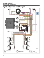
Page 92: ...19 18 17 16 15 14 26 25 24 23 22 21 20 10 9 8 7 6 5 4 3 2 1 19 18 17 16 15 14 13 12 11 29 28 27 26 25 24 23 22 21 20 1 2 3 3 2 1 6 5 4 9 6 4 3 5 1 7 7 J1 A J1 B J2 3 1 4 2 J1 A J1 B J2 7 7 2 8 010361 1 2 3 1 2 3 7 5 6 7 1 2 3 1 2 3 1 2 3 3 2 1 6 5 4 3 2 1 A B 1 Key switch stop circuit 2 Fuse 3 Stator 4 EMM 5 Crankshaft position sensor 6 Capacitor 7 Ignition coil 8 Main harness ground 9 Solenoid 12...

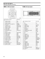
Page 93: ...stic connector White 4 Ground water in fuel digital Black 5 Oil level switch Tan Black 6 Crankshaft position sensor CPS Yellow 7 Ground CPS digital White 8 Bootstrap connector programming Blk Orange 9 Stop circuit Blk Yellow 10 Sensors 5 V Red 11 Ground analog Black 12 Engine temperature sensor port Pink Black 13 CANbus NET L Blue 14 CANbus NET H White 15 Water pressure Pink 16 Tachometer Gray 17 ...

Page 94: ...der 2 Orange Blue 20 Injector cylinder 4 Purple 21 Switched B 12V Purple 22 Injector ground Black 23 Oil solenoid Blue 24 Rear oil injector 12 V Red Yellow 25 Ignition cylinder 6 Orange Green 26 Ignition cylinder 1 Orange Blue 001876 004046 Pin No Description of Circuit Wire Color 1 B Red 2 vacant 3 Isolated B Red Black 4 Battery ground Black 5 Battery ground Black 6 vacant 7 Winding 1S Yellow 8 W...

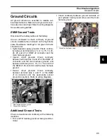
Page 95: ...onnector and the main harness ground Injector circuit grounds Check continuity between terminal pins 9 and 27 of the EMM J2 connector and the main harness ground and between terminal pins 9 10 15 16 and 22 of the EMM J1 B connector and the main harness ground Sensor circuit grounds Check continuity between terminal pins 4 and 11 of the EMM J1 A connector and the appropriate sensor ground connectio...

Page 96: ...returning to the EMM IMPORTANT Use Evinrude Diagnostics soft ware to monitor sensor circuit voltages or values Crankshaft Position Sensor CPS Test Use the Evinrude Diagnostics software CPS Sync and engine RPM displays to confirm a valid CPS signal while the outboard is cranking or running An RPM display higher than zero indicates a CPS signal to the EMM Disconnect the crankshaft position sensor Us...

Page 97: ... must change evenly as the sensor lever is moved Connect red meter lead on terminal B and black meter lead to terminal C Rotate the sensor lever Resistance reading must change evenly as the sensor lever is moved Engine Temperature Sensor Test Remove the electrical connector from the engine temperature sensor Use a digital multimeter to measure sensor resis tance Air Temperature Sensor AT Test Remo...

Page 98: ...ition module of EMM is also powered by the 55 VDC output Stator Resistance Tests Use a digital multimeter to check resistance of sta tor windings Disconnect EMM J2 connector from EMM Connect meter leads to the following pins Yellow white and yellow pins 17 and 7 Brown white and brown pins 28 and 8 Orange white and orange pins 18 and 10 IMPORTANT A reading of less than 2 ohms is acceptable Make sur...

Page 99: ...ANT The regulator requires voltage to operate Before proceeding make sure there is at least 7 V on the positive terminal of the starter so lenoid Disconnect the battery cables at the battery Use an inductive amp meter or connect a 0 to 50 A ammeter in series between the red wire s of engine wire harness alternator output from EMM and the positive B battery cable terminal of starter solenoid IMPORT...

Page 100: ...ng of these tests and remain connected to the outboard during the tests Check battery ground cable for continuity With the key switch OFF check battery voltage at auxiliary battery then check voltage at auxiliary battery connection If the readings are not the same replace wire to auxiliary battery The auxil iary battery wire must be at least 10 gauge and it must be protected by a 50 A fuse or circ...

Page 101: ...n white red wires at J2 connector of EMM Voltage at EMM connector should be approximately 30 V With outboard running at 1000 RPM voltage on white red wires should increase to 55 V Voltage readings at a specific speed RPM should be steady If there is any other reading refer to Stator Tests on p 98 Inspect the stator wiring and connec tions Inspect the capacitor wiring connections and capacitor Repa...

Page 102: ...7 26 25 24 23 22 21 20 1 2 3 A B A B 4 5 6 J1 A J1 B J2 J1 A J1 B J2 010362 3 2 6 1 5 7 17 4 8 9 15 13 2 3 12 16 10 11 1 Marine battery 2 RED wire POS 3 BLACK wire NEG 4 Starter solenoid 5 Fuse 10 amp 6 RED PURPLE wire 7 Key switch connectors 8 Ignition switch 9 PURPLE wire switched B 10 26 pin J1 B EMM connector 11 34 pin J1 A EMM connector 12 Engine Management Module EMM 13 YELLOW RED wire start...

Page 103: ...ovides switched 12 V to solenoid terminal A and EMM Yellow red wire provides switched 12 V to EMM Brown white wire from terminal 11 of EMM J1 B connector provides switched ground NEG to starter solenoid terminal B Instrument Wire Harness Contains the following circuits Red purple wire provides 12 V to key switch ter minal B Purple wire provides switched 12 V to engine wire harness Yellow red wire ...

Page 104: ...nd NEG to terminal B of solenoid Measure resis tance between the starter positive cable termi nal and the positive battery cable terminal The solenoid must close with an audible click Meter must show continuity low reading If meter shows no continuity high reading replace the solenoid After re installing the solenoid coat all wires and terminals with Black Neoprene Dip Starter Voltage Drop Test 1 ...

Page 105: ...able of solenoid terminal Connect negative lead to starter motor terminal Activate starter motor and observe voltage reading No Load Current Draw Test Securely fasten starter in a vise or suitable fixture before proceeding with this check Use a battery rated at 500 CCA 60 amp hr or higher that is in good condition and fully charged IMPORTANT The driven gear and pinion as sembly must be removed for...

Page 106: ...nal C of the key switch is NOT used Neutral Start Circuit Test Use an ohmmeter or continuity light to test the continuity of the circuit while positioning the remote control in NEUTRAL FORWARD and REVERSE IMPORTANT Turn propeller shaft or disconnect shift cable to allow proper remote control shift ac tion while outboard is not running Disconnect the instrument harness connector from the key switch...

Page 107: ...can be part of the key switch or installed as a separate switch Either style con nects the M terminals of the key switch The emergency stop switch function grounds the stop circuit wire black yellow when the lanyard clip is removed One M terminal is the ground wire black and one M terminal is the stop circuit wire black yellow Install the clip on the emergency stop switch or key switch Start the o...

Page 108: ...d B connec tion to TNT motor Terminals 87 and 30 are normally open B is applied to terminal 30 when relay is activated This supplies ground B connection to TNT motor Refer to Tilt and Trim Module Diagram Test Procedure Make sure red and black wires are connected to 12 V battery power supply Set voltmeter to 12 VDC scale Connect test leads to terminals A and B of TNT motor connector Use a wire jump...

Page 109: ... turn on turn the key switch OFF Disconnect the gauge 8 pin connec tor from the back of the gauge and turn the key switch ON Test for battery voltage between instrument harness terminal 1 purple wire and terminal 2 black wire If battery voltage is present replace the gauge If there is no battery voltage check that 12 V is present at terminal B of the key switch Check condition of the instrument ha...

Page 110: ...MP HOT Circuit Test The tan wire of engine harness and the MWS har ness receives a signal from the EMM The EMM receives information from the temperature sensor on the cylinder head Using a jumper wire connect tan wire pin 6 of the engine harness connector to a clean engine ground Turn the key switch ON After the normal self test sequence the gauge WATER TEMP HOT indi cator should stay on If LED is...

Page 111: ...and reconnect all discon nected circuits Tachometer Circuit Tests Check voltage at the battery Use this reading as a reference for battery voltage Connect the red meter lead to the tachometer pur ple wire and the black meter lead to the tachome ter black wire key ON outboard NOT running If meter shows battery voltage go to next step If meter shows less than battery voltage check the purple red pur...

Page 112: ...grease to the threads of the puller pressing screw P N 307637 and the center hole of the crankshaft Place the puller on flywheel with body flat side up Attach the puller body with the three shoulder screws and washers Hold puller body with han dle and tighten pressing screw until flywheel releases Turn the center screw and lift the fly wheel off of the crankshaft Stator Service Remove six allen he...

Page 113: ...lywheel IMPORTANT DO NOT over apply Nut Lock on flywheel taper This prevents Nut Lock from mi grating into upper seal of crankshaft Align the flywheel keyway and install the flywheel Coat the threads of the flywheel nut with Gasket Sealing Compound Install the nut and tighten to a torque of 140 to 160 ft lbs 190 to 217 N m IMPORTANT Perform the timing verification procedure after flywheel removal ...

Page 114: ...t with four screws Tighten screws to a torque of 60 to 84 in lb 7 to 9 5 N m Install spark plug leads with ground screw Tighten screw securely Ignition Coil Installation Connect ignition coil electrical connector Place electrical connector on its retainer Install one rubber washer on each screw Install screw through ignition coil Install remaining rubber washers on screws between coil and bracket ...

Page 115: ... the pointer Label this mark A Rotate the flywheel clockwise until the piston contacts the tool Mark the flywheel directly across from the pointer Label this mark B Rotate fly wheel counterclockwise slightly to release tool then remove it from spark plug hole Use a flexible measuring device such as a piece of string to find the exact center between marks A and B Measure along the edge of the fly w...

Page 116: ...timing adjustments TPS Calibration Use Evinrude Diagnostics software to tell the EMM what throttle position sensor voltage is when the throttle plates begin to open Set TPS Calibration after replacing or adjusting any throttle body or throttle linkage parts Remove the air silencer Turn the key switch to the ON position Do NOT start the outboard Models with ICON Electronic Shift and Throttle Rotate...

Page 117: ...e screen will increase Click the Working button in the software to cali brate the TPS Models with ICON Electronic Shift and Throttle Use Ball Socket Installer P N 342225 to install throttle link onto actuator arm Return the ICON remote control to the NEUTRAL position The throttle actuator should move the throttle plates to the idle position All Models Connect the crankshaft position sensor CPS Ins...

Page 118: ...o the starter bearings and commutator Disconnect the battery cables at the battery Remove the starter positive cable from post on starter Remove the four frame and bracket mounting screws Lift and remove the starter Loosen the two nuts used to fasten the starter bracket Remove the nuts and bracket Remove the screws lock washers and pinion housing Starter Disassembly Lift and remove the wave washer...

Page 119: ...ing ring under the spacer Remove the retaining ring spacer and spring from pinion shaft Remove pinion and plastic weather cover from pinion shaft Remove the driven gear and thrust washer Using No 2 external retaining ring pliers remove the retaining ring and drive gear from the armature shaft 30371 30360 30369 30368 30367 30366 ...

Page 120: ...e with a rubber mallet to loosen it Find the insulator cap end of the shaft or inside the end cap Inspect and replace if necessary Note the alignment marks by the positive terminal stud Hold the armature in place and slide the frame away from the gear housing Slowly remove the armature and thrust washer Do not lose the brush springs 30365 30354B 30352 30351 ...

Page 121: ...damaged windings Clean off any carbon deposits or foreign matter which could contribute to failure of wind ings Check permanent magnets Make sure they strongly attract any steel or iron object held inside frame Weak magnetism could cause excessive RPM on No Load Current Draw Test on p 105 After disassembling the drive clean each part with Cleaning Solvent and inspect for wear and distor tion If th...

Page 122: ...sh es could damage the starter or cause reverse rota tion Apply Moly Lube to the armature bushing Install the thrust washer and armature Align the starter frame and make sure the long alignment mark matches the mark next to the pos itive terminal stud on the gear housing Push the armature down firmly and slide the frame into place Align the notches in the gear housing and frame Install insulator c...

Page 123: ...rnal retaining ring pliers Lightly coat the gear housing bearing with Moly Lube Lightly coat the driven gear with Triple Guard grease Install the thrust washer and driven gear Install the weather cover If removed install the spring and spacer large diameter up on the pinion shaft Secure with retaining ring Install bushing and wave washer convex side down Lightly coat the pinion shaft splines helix...

Page 124: ...hten to a torque of 50 to 65 in lbs 5 6 to 7 3 N m To test the assembly and operation of the starter refer to No Load Current Draw Test on p 105 Starter Installation Apply Locquic Primer and Nut Lock to the threads of the four starter mounting screws Position the starter and install the screws and lock washers First tighten the top two screws then the bottom two screws to a torque of 168 to 192 in...

Page 125: ...he seal is in place Clean off any old grease and dirt from connectors Apply a light coat of Electrical Grease to seal only Push connectors together until latched Terminal Removal Use hook end of Connector Service Tool P N 342667 to pull out wedge from receptacle or use other end of tool to pry out wedge from plug Use needle nose pliers to remove wedge from 3 pin receptacle Release terminal latch a...

Page 126: ...leave no loose strands Crimp wire securely Do not solder Crimp insulation in 14 16 gauge notch of crimping pliers AMP Connectors IMPORTANT Always use the appropriate meter test probes and adapters when testing compo nents fitted with these terminals Electrical grease is NOT used on AMP connectors Superseal 1 5 Disconnect Lift latch Pull connectors apart Connect Confirm the seal is in place Push co...

Page 127: ...at device in connector Crimping Terminals Crimping Superseal 1 5 terminals requires AMP Crimp Tool with dies P N 777281 Super Seal The J1 A and J1 B connectors of the EMM are AMP Super Seal connectors Disconnect Depress BOTH latches and pull connector from plug Connect Push connector into plug until latches engage 1 Anti backout device plug 2 Anti backout device receptacle 002449 002450 1 Locking ...

Page 128: ... the EMM is a AMP Power Timer Series connector Disconnect Use a screw driver to open latch Pull connector from plug Connect Push connector until seated in plug Close latch completely Terminal Removal Use Terminal Release Tool P N 351413 to release BOTH locking mechanisms of connector Pull terminal from housing 1 Latch 2 Lock mechanism 002453 1 Terminal 002454 2 1 2 1 2 1 1 J2 connector 2 Latch clo...

Page 129: ...by releas ing the tab and then pushing the terminal and wire through connector housing Insert a thin tool into the connector above the ter minal to release tab Terminal Installation Install wire gasket on wires and feed wires through the correct terminal position of the con nector housing Terminal is crimped onto wire and then pulled back into connector housing until lock ing tab engages and termi...

Page 130: ...Electrical and Ignition Notes 130 Notes Technician s Notes Related Documents Bulletins Instruction Sheets Other ...

Page 131: ... Priming 142 Vent Line Clamp 142 Priming the Fuel System 142 Fuel System Tests 143 Fuel System Pressure Test 143 Pressure Regulator Test 143 Vapor Separator Vent Check 144 Fuel Injector Pressure Test 144 Fuel Injector Resistance Test 144 Circulation Pump Resistance Test 145 Lift Pump Pressure Test 145 Lift Pump Vacuum Test 146 Lift Pump Diaphragm Test 146 Anti Siphon Valve Test 146 Fuel Component ...

Page 132: ... m 006971R 60 84 In lbs 7 9 5 N m L 100 110 In lbs 11 12 N m P Lower screw only L L L Hand tighten the fuel filter until the seal contacts the filter housing Then tighten an additional one half to one turn A Triple Guard Grease B Gasket Sealing Compound C Adhesive 847 E Red Ultra Lock F Blue Nut Lock H Outboard Engine Lubricant L Pipe Thread Sealing Compound X see Service Manual ...

Page 133: ...lbs 8 11 N m F 96 120 in lbs 11 13 5 N m 10 18 in lbs 1 2 N m X 60 84 in lbs 7 9 5 N m C B B 004099 A Triple Guard Grease B Gasket Sealing Compound C Adhesive 847 D Moly Lube E Red Ultra Lock F Blue Nut Lock G Needle Bearing Grease K Purple Screw Lock X see Service Manual IMPORTANT Do NOT lubricate TPS to throttle shaft surface Bond seals to air silencer ...

Page 134: ...e H Outboard Engine Lubricant S STP Oil Treatment R R R R R R R R S S S S S S S S S S R H 24 36 in lbs 2 7 4 N m S A A 5 ft lbs 7 N m 24 26 Ft lbs 33 35 N m 10 ft lbs 14 N m 1 2 3 004101R S Supply R Return A Triple Guard Grease B Gasket Sealing Compound C Adhesive 847 E Red Ultra Lock F Blue Nut Lock H Outboard Engine Lubricant S STP Oil Treatment X see Service Manual Tighten in 3 stages ...

Page 135: ...odels 1 Fuel supply from boat fuel system 2 Fuel lift pump 2 to 8 psi 3 Pulse hose s from cylinder crankcase 4 Water separating fuel filter 5 Fuel supply to vapor separator 6 Vapor separator 7 Vent hose to throttle body 8 Electric fuel circulation pump 20 to 35 psi 9 Fuel supply manifold 10 Fuel injector s 11 Fuel return manifold 12 Pressure regulator high pressure 13 Test fitting low pressure 14 ...

Page 136: ...13 12 11 10 9 8 19 18 17 16 15 14 26 25 24 23 22 21 20 10 9 8 7 6 5 4 3 2 1 19 18 17 16 15 14 13 12 11 29 28 27 26 25 24 23 22 21 20 2 1 2 1 2 1 2 1 2 1 1 2 J1 A J1 B J2 3 1 4 2 J1 A J1 B J2 1 1 010369 1 1 1 2 1 5 6 1 7 5 8 2 4 3 3 6 6 1 Injectors 2 EMM 3 55 V circuit white red 4 Capacitor 5 Grounds neg 6 Fuel Injector grounds 7 High pressure fuel pump 8 Fuel filter water separator ...

Page 137: ...at sources and open flames Close the vent screw of the fuel tank cap if equipped to prevent escape of fuel or fuel vapors which could accidentally ignite Do not allow disconnected fuel hoses to leak fuel NOTICE Do not use portable fuel tanks for outboards larger than 115 HP Inadequate fuel flow to high horsepower outboards can result in serious powerhead damage 15 30 HP 40 90 HP 115 300 HP Fuel ta...

Page 138: ...damage the out board Additives IMPORTANT The only fuel additives approved for use in Evinrude outboards are 2 4 fuel condi tioner and Evinrude Johnson Fuel System Clean er Use of other fuel additives can result in poor performance or engine damage Evinrude Johnson 2 4 Fuel Conditioner will help prevent gum and varnish deposits from form ing in fuel system components and will remove moisture from t...

Page 139: ...tor and the high pressure components of the fuel system from contaminants Refer to Inspection and Mainte nance Schedule on p 18 for service frequency Vapor Separator The vapor separator Serves as a water cooled fuel reservoir to accu mulate incoming fuel from the fuel lift pump and from the fuel return manifold Contains a float controlling the venting of fuel vapors Contains a fuel pressure regula...

Page 140: ...he fuel system Fuel returning from the injectors enters the fuel chamber of the vapor separator through a pres sure regulator The pressure regulator maintains approximately 20 to 30 psi 138 to 207 kPa of fuel pressure in the high pressure side of the fuel sys tem Fuel Circulation Pump The fuel circulation pump is an electric high pres sure fuel pump Fuel Supply The pump is mounted to the vapor sep...

Page 141: ...compensate for vari ations in fuel flow Each injector and its location on the outboard is identified by the EMM DO NOT install an injector without updating the compensa tion software Each service injector includes its fuel flow infor mation on a 3 5 in floppy disk This software allows the EMM to be reprogrammed for this injec tor s unique fuel flow characteristics Injector Fuel Supply Fuel is supp...

Page 142: ... fuel primer until fuel flows from the fuel hose Once fuel flow is observed connect fuel supply hose from fuel tank to hose fitting on outboard Secure hose with Oetiker clamp Use the primer to fill the vapor separator The high pressure fuel circuits and injectors will prime as the outboard is cranked with the starter Observe all fuel lines both in the boat and on the outboard Repair any fuel leaks...

Page 143: ...pair or replace as needed Restricted fuel filter water separator assembly Lift pump not supplying adequate fuel to vapor separator Refer to Lift Pump Pressure Test on p 145 If the above tests are good and vapor separator remains full of fuel check for damaged circula tion pump Replace vapor separator assembly No pressure Check electrical circuit and ground connections for circulation pump If volta...

Page 144: ...at the battery Relieve fuel system pressure See Relieving Fuel System Pressure on p 147 IMPORTANT Perform test with injector mounted to cylinder head and fittings installed with manifold retainer Use cap and tie strap to seal off outlet fitting Con nect a 0 to 30 psi 0 to 207 kPa pressure tester to the inlet fitting Pressurize the injector to 30 psi 207 kPa Pressure must hold for at least five min...

Page 145: ...el pressure test fitting Prime the fuel system and check for leaks START outboard and run at idle speed Hold gauge level with inlet fitting and monitor gauge for pressure reading Pressure should stabilize and gauge must not indicate less than 4 psi 27 kPa Results Normal pressure Perform the Lift Pump Vacuum Test on p 146 Make sure no air leaks or restrictions exist in the fuel supply hose or boat ...

Page 146: ...mp Diaphragm Test Perform this test only if a damaged pump is sus pected This test does not check the performance of internal fuel pump check valves Remove both pulse hoses from the crankcase fit tings Apply 15 psi 103 kPa to each of the pulse hoses of the pump Replace lift pump if either side of pump fails to hold pressure Anti Siphon Valve Test Remove anti siphon valve from fuel tank Install ada...

Page 147: ... appropriate filter wrench to turn the filter in a counterclockwise direction Remove the filter carefully to prevent spilling the filter s contents WARNING Gasoline is extremely flammable and highly explosive under certain conditions Use cau tion when working on any part of the fuel sys tem Protect against hazardous fuel spray Before starting any fuel system service carefully relieve fuel system p...

Page 148: ... fuel lift pump is serviceable as a complete assembly Refer to parts catalog for service parts Removal Disconnect the battery cables at the battery Disconnect the fuel supply hose from the in line fitting Disconnect the fuel outlet hose from tee Disconnect the fuel lift pump pulse hoses at the crankcase fittings Remove clamp screw clamp and oil injection pump from fuel pump bracket Loosen the fuel...

Page 149: ...p and vapor vent hose from separator cover Remove clamps and vapor separator cooling water hoses Remove clamps and fuel return manifold and fuel supply hose from bottom of vapor separator Remove the vapor separator housing retainer clip Remove vapor separator fuel pump from the mounting stud and slide vapor separator housing from the grooves of the isolator mounts Installation Slide the vapor sepa...

Page 150: ...uel ports Install retainer in the outer groove of the manifold fittings Install and tighten screw to a torque of 24 to 36 in lbs 2 7 to 4 N m Install the fuel manifolds to the fuel pump assem bly and secure with clamps Fuel supply manifold to circulation pump Fuel return manifold to vapor separator 1 Fuel supply manifold 2 Fuel return manifold 004189 1 Retainer screw 2 Fuel supply manifold fitting...

Page 151: ...ed fuel with shop towels Crush Ring Replacement Use Injector Puller Kit P N 356461 to remove injector from mounting cup Turn the nut of the fuel injector puller counter clockwise several turns Place the fuel injector puller on the fuel injector housing NOTICE Fuel injectors must be installed in the correct cylinder locations Use Evinrude Diagnostics Software to make sure that EMM program ming matc...

Page 152: ...e Turn the puller nut until the fuel injector is removed from the fuel injector housing Remove fuel injector puller from injector Remove crush ring and O rings from injector Inspect and clean injector filter Install new crush ring and O rings Lubricate O rings with STP Oil Treatment Install injector into mount housing Press on injec tor face until injector seats in mount housing 1 Angled edge of t...

Page 153: ...oefficient file location The coefficient file name must match the serial number of the injector Select the correct file for the injector Select the Replace Injector button After the upload is complete the program will return to the Cylinder tab Make sure the serial number displayed on the screen matches the serial number printed on the serial number label of the replacement injector Install Inject...

Page 154: ...hrough mounting flange of injector and into cylinder head Tighten screws in stages starting with the lower screw First torque is 5 ft lbs 7 N m Second torque is 10 ft lbs 14 N m Final torque is 24 to 26 ft lbs 33 to 35 N m Reconnect fuel injector electrical connectors Install fuel manifolds Refer to Fuel Manifold Ser vice on p 149 Intake Manifold Service Removal Disconnect vapor separator vent hos...

Page 155: ...on Inspect the leaf plate assemblies for damage or contamination Leaf plates must not be distorted Leaf valve must not be cracked or chipped Leaf plate stops must not be distorted or loose Leaf plate assemblies must be clean Inspect the intake manifold All gasket surfaces must be cleaned smooth and free of nicks Use a machinist s straight edge and a feeler gauge to check flatness in all directions...

Page 156: ...ghten in stages to a final torque of 96 to 120 in lbs 11 to 13 5 N m Place gasket on throttle body Install throttle body with oil pump bracket on reed plate and install screws Tighten the center screws first and expand out ward Final torque is 60 to 84 in lbs 7 to 9 5 N m Install crankshaft position sensor Install vapor separator vent hose and oil recircula tion hose Secure with tie straps Connect...

Page 157: ...157 Fuel System Fuel Component Servicing 7 Position clamps as shown Refer to TPS Calibration on p 116 1 Clamps 2 Idle air hose 3 Oil fuel pump bracket 006990 3 2 1 1 ...

Page 158: ...Fuel System Notes 158 Notes Technician s Notes Related Documents Bulletins Instruction Sheets Other ...

Page 159: ...OIL Warning 170 NO OIL Warning 170 Cylinder and Crankcase 170 Oil Recirculation System 171 Oil Control Settings 173 Oil Injection Rate 173 Break In Oiling 174 Oil Supply Priming 175 Oiling System Tests 178 Oil Injection Pump Static Test 178 Oil Injection Pump Voltage Tests 178 Oil Injection Pump Circuit Resistance Test 179 Cylinder Oil Pump Voltage Tests 180 Cylinder Oil Pump Resistance Test 181 O...

Page 160: ...o Evinrude Johnson XD100 oil Refer to the Operator s Guide for Oil Requirements NOTICE 355624 355627 NOTICE This outboard has been programmed for the use of Evinrude Johnson XD100 outboard oil ONLY Failure to use Evinrude Johnson XD100 outboard oil may harm engine performance and shorten engine life IMPORTANT This outboard has been programmed for the use of Evinrude Johnson XD100 outboard oil ONLY...

Page 161: ...J1 B J2 010370 6 5 4 2 1 1 2 3 4 5 3 2 1 A B 13 14 4 11 10 7 12 15 6 5 3 2 8 1 9 1 Crankcase Oil Injection Pump 2 Cylinder Oil Injection Pump 3 4 L models only 3 EMM 4 55 V circuit White Red 5 Capacitor 6 Grounds NEG Black 7 EMM to Oil Pump Blue 8 Oil Pressure Sensor 5V analog Red 9 Oil Pressure Sensor Signal Tan White 10 Rear Oil Injector control Blue Red 3 4 L models only 11 Rear Oil Injector 12...

Page 162: ...delivers oil to Rear oil manifold Crankcase fittings 1 Cylinder 1 2 Cylinder 2 3 Cylinder 3 4 Cylinder 4 5 Cylinder 5 6 Cylinder 6 7 Rear oil manifold 1 Cylinder 2 2 Cylinder 4 3 Cylinder 6 4 Cylinder 1 5 Cylinder 3 6 Cylinder 5 1 Oil Tank Assembly 2 Oil Pick up Filter 3 Oil Supply Hose 4 Inline Oil Filter 5 Oil Injector Assembly 6 Primary Oil Manifold 7 Oil Pressure Sensor 8 Oil Distribution Hose...

Page 163: ...Oiling System Oil Supply Diagrams 163 8 008208R Port Side View Starboard Side View ...

Page 164: ...old delivers oil to Crankcase fittings 1 Cylinder 1 2 Cylinder 2 3 Cylinder 3 4 Cylinder 4 5 Cylinder 5 6 Cylinder 6 1 Cylinder 2 2 Cylinder 4 3 Cylinder 6 4 Cylinder 1 5 Cylinder 3 6 Cylinder 5 1 Oil Tank Assembly 2 Oil Pick up Filter 3 Oil Supply Hose 4 Inline Oil Filter 5 Oil Injector Assembly 6 Primary Oil Manifold 7 Oil Pressure Sensor 8 Oil Distribution Hoses 9 Rear Oil Pump ...

Page 165: ...Oiling System Oil Supply Diagrams 165 8 008432R Port Side View Starboard Side View ...

Page 166: ...166 Oiling System Oil Recirculation Diagrams Oil Recirculation Diagrams 2 4 6 1 3 5 008205R Complete View 008206R Top View ...

Page 167: ...Oiling System Oil Recirculation Diagrams 167 8 008207R Starboard View Port View ...

Page 168: ...sts of the following compo nents Oil tank Oil injection pump and manifold assembly Oil pressure sensor Electrical circuit LOW OIL and NO OIL warning systems Cylinder and crankcase Rear oil manifold assembly 3 3 L models Rear oil pump 3 4 L models Oil recirculation system Oil Tank Assembly The oil tank must be properly positioned and the oil level must be monitored Refer to the Predeliv ery and Ins...

Page 169: ...in oil manifold pressure The EMM supplies and moni tors electrical current to the sensor The sensor provides an output voltage to the EMM based on oil manifold pressures 5 VDC Input on RED wire 0 5 4 5 V Output on TAN WHITE wire Ground on BLACK wire The EMM monitors the oil pressure sensor s elec trical circuit If circuit voltage is beyond the speci fied range 0 15 V 4 85 V the EMM If oil pressure...

Page 170: ...uit is open the EMM LOW OIL Warning A sending unit in the oil tank pick up assembly monitors the oil level in the oil tank If the oil level falls below one quarter capacity the EMM signals An optional oil tank sending unit kit is available to display actual oil level through an I Command net work NO OIL Warning The EMM monitors the electrical circuit of the oil pressure sensor If the sensor or cir...

Page 171: ... recirculate any accumulation of oil from various locations in the powerhead The movement of oil is controlled by check valves Cylinder Recirculation Internal powerhead oil drain passages connect the lowest point of the intake port area of the cylin der block to external check valves External hoses connect these check valves to a hose fitting pressed into the top of the intake manifold throt tle b...

Page 172: ...sages in the crankcase Oil migrates to the bearings from the crankcase areas of the higher cylinders The lower main bearing receives oil through a grooved passage in the crankcase Lower to upper main bearing oil flow Oil moves from the lower main bearing cavity through an internal crankcase passage to an external fitting External hoses with an in line check valve connect to a fitting at the upper ...

Page 173: ... oil in extreme applications The XD100 setting provides an option to run the outboard at a reduced oil injection rate This set ting REQUIRES the use of Evinrude XD100 out board lubricant and is not recommended for all applications IMPORTANT The XD100 setting is not available on all models Use the XD100 setting for Conventional use runabouts cruisers Moderate applications Powerhead oil programming ...

Page 174: ...ls The EMM automatically supplies extra oil to the engine as follows 90 V6 First two hours above 2000 RPM Follow these steps for outboard set up Use Evinrude Diagnostics software to make sure the break in program has been started on a new outboard Use the diagnostics software to start break in oiling after a powerhead rebuild XD100 Outboard Oil Decal 355627 NOTICE The operator must monitor the oil...

Page 175: ...e the oil priming functions in the software to make sure the system is com pletely primed IMPORTANT The outboard should be running during the priming procedure to avoid pumping too much oil into the crankcase which could cause a hard starting condition Prime the rear oil pump FIRST cylinder oil pump Use the Prime Cylinder Oiler button of the Dynamic Test screen to prime the rear oil pump With the ...

Page 176: ...ntinued priming Repair any fuel or oil leaks 200 250 HP 3 3 L Models Start the outboard Use the oil priming function in the software to make sure the system is com pletely primed Use the Prime Oil System button of the Dynamic Test screen to prime the oil pump Dynamic Tests Screen 1 Prime Oil System button 008570L 1 Crankcase oil pump 2 Oil distribution hoses 008392 1 2 1 1 Oil distribution hose 2 ...

Page 177: ...k fittings Small bubbles are acceptable Large bubbles must be eliminated through continued priming Repair any fuel or oil leaks The oiling system on these models can also be primed using the Self Winterizing feature if diag nostics software is not available Refer to Storage on p 48 1 Oil distribution hoses 004224 1 Rear oil distribution manifold 008203 1 Oil distribution hose 2 Small bubbles 3 Lar...

Page 178: ...for an audible click from the oil injection pump when it is activated Use an inductive timing light to monitor current flow through the ground circuit blue wire at the oil pump connector pin 2 If the light flashes the EMM and oil injection cir cuits are not at fault Refer to Oil Injection Pump Voltage Tests on p 178 Oil Injection Pump Voltage Tests Use a digital multimeter calibrated to a scale th...

Page 179: ...jection Pump Circuit Resistance Test IMPORTANT The complete oil injection pump electrical circuit includes EMM alternator output the engine wire harness the injection pump wind ing and connectors and the oil injector control cir cuit of the EMM Check continuity of all wiring and connections Disconnect the battery cables at the battery Disconnect J1 B connector from EMM Use a digi tal multimeter wi...

Page 180: ...ultimeter to the Hertz Hz scale Meter should read approximately 2 Hz Results If voltage and control signal readings Hz at pin A are within range the EMM and wiring are not at fault If voltage at pin A is not within range check volt age at pin B red yellow wire of the oil pump electrical connector Connect positive meter lead to pin B red yellow wire of oil injection pump electrical connector Observ...

Page 181: ...e oil pickup and remove the oil supply hose from the oil injec tion pump Use low pressure air to purge oil from hose Clean up any spilled oil with shop towels Use Plug Holder P N 329661 and clamp to plug the pickup end of the hose Attach a vacuum tester to the outboard side of oil supply hose and draw 7 in Hg 24 kPa vacuum on the hose for at least five minutes Repair or replace any leaking compone...

Page 182: ...oil with shop towels Results Oil flows from distribution hose compare to oil flow at other distribution hoses If one or more hoses fail to discharge oil check for a kinked or restricted hose before replacing the oil injection pump assembly Oil Injection Fittings Flow Test Make sure the oil injection fittings of the cylinder and crankcase assembly allow fluid to move Remove oil distribution hose fr...

Page 183: ...val Release the hose by depressing the outer ring of the hose retaining mechanism Clean up any spilled oil with shop towels ENVIRONMENTAL NOTE Dispose of used oil or oil contaminated towels in an environmentally responsible manner or according to local regulations WARNING To prevent accidental starting while servic ing disconnect the Crankshaft Position Sen sor CPS Oil Distribution Hose Length Pri...

Page 184: ...ctor IMPORTANT Note oil distribution hose routings before proceeding with disassembly Center hose from primary oil manifold connects to oil to inlet of rear oil manifold Remove oil distribution hoses from the crankcase fittings Remove oil injection pump clamp screw Remove the oil injection pump assembly Clean up any spilled oil with shop towels IMPORTANT The oil injection pump and mani fold is an ...

Page 185: ...Check oil flow through oil distribution hoses Check oil system operation and routing of oil hoses Refer to Oil Supply Priming on p 175 Run the outboard and check for leaks Repair any oil leaks and any kinked or misrouted hoses Rear Oil Pump Removal Disconnect the battery cables at the battery Remove engine cover Remove the oil supply hose from the fitting inlet of the oil pump Disconnect the elect...

Page 186: ...t with two screws Tighten screws to a torque of 24 to 36 in lbs 2 7 to 4 N m Install the oil injection pump and bracket with two mounting bracket screws Tighten to a torque of 60 to 84 in lbs 7 to 9 5 N m Route oil distribution hoses from the oil distribu tion manifold to the crankcase oil delivery fittings as they were before removal Refer to Oil Supply Diagrams on p 162 1 Fitting inlet 2 Mountin...

Page 187: ...p as shown Connect the battery cables at the battery Make sure oiling system is primed Check oil flow through oil distribution hoses Check oil system operation and routing of oil hoses Refer to Oil Supply Priming on p 175 Run the outboard and check for leaks Repair any oil leaks and any kinked or misrouted hoses Install engine cover 1 Cylinder sleeve oil fittings port 008456 1 Cylinder sleeve oil ...

Page 188: ...Oiling System Notes 188 Notes Technician s Notes Related Documents Bulletins Instruction Sheets Other ...

Page 189: ...rmostats 193 Block Venting 193 Operation 194 Cylinder Block Cylinder Head Cooling 194 EMM and Vapor Separator Cooling 195 Engine Temperature Check 195 Software Method 196 Pyrometer Method 196 Idle Operating Temperature Troubleshooting Below Range 196 Temperature Sensor Servicing 198 Removal 198 Installation 198 Thermostat Servicing 199 Disassembly 199 Inspection 199 Assembly 199 Pressure Relief Va...

Page 190: ...pter housing Water supply adapter to cylinder block port and starboard Water supply to EMM cylinder block vent Water supply EMM to vapor separator Vapor separator water outlet to adapter Port thermostat tower to blow off valve Blow off valve to port cylinder head Starboard thermostat tower to blow off valve Blow off valve to starboard cylinder head Water supply to propeller hub cooling Outgoing wa...

Page 191: ...3 Water intake screens Water pump Water tube Adapter housing Water supply adapter to cylinder block port and starboard Water supply to EMM cylinder block vent Water supply EMM to vapor separator Vapor separator water outlet to adapter Port thermostat tower to blow off valve Blow off valve to port cylinder head Starboard thermostat tower to blow off valve Blow off valve to starboard cylinder head W...

Page 192: ...at LOW speeds below 1500 RPM and as a centrifugal pump at HIGHER speeds Refer to Water Pump Service in the Gearcase service manual for water pump servicing Water Supply Tube The water pump outlet connects with the water supply tube located in the outboard s midsection Grommets seal the water tube to the water pump housing and the inner exhaust housing On 3 3 L models the water tube fastens to the ...

Page 193: ...he valve from closing completely Thermostats Thermostats control water flow and operating tem perature at lower speeds below 1200 RPM Overheating A restricted or faulty thermostat typ ically results in LOW SPEED overheating Overcooling Debris may prevent the thermostat from closing completely Block Venting A fitting and hose from the top of the block allows the constant movement of water and or ai...

Page 194: ...alve at approximately 1200 RPM Water flows through the valve and bypasses the thermostats Hoses route the water flow from the pressure valve to the vertical water passages below the thermostats All water flows through the cylinder heads to the outlet passages of the block and then exits through the adapter housing This pressure controlled water outlet circuit pro vides a high flow discharge of wat...

Page 195: ...e Temperature Check IMPORTANT The engine temperatures listed below are based on an intake water temperature of 70 10 F 21 3 C Install correct test propeller and place outboard in a test tank or in the water Start outboard and run at 3000 RPM in FORWARD gear for at least five minutes Remember running outboards at high speeds in test tanks may disrupt water flow to gearcase water intakes Make sure t...

Page 196: ...Check temperature on both sides of powerhead Typical pyrometer readings at IDLE speed should be 143 F 15 F 62 C 8 C IMPORTANT If you get low or inaccurate read ings with a digital pyrometer coat the probe loca tion with Thermal Joint Compound P N 322170 Idle Operating Temperature Troubleshooting Below Range If engine IDLE temperature is below operating range 160 F 10 F 71 C 6 C check thermo stat a...

Page 197: ... eliminating water flow to the cylinder heads pressure relief valve is leaking Replace pressure relief valve If IDLE temperature is still below operating range with hoses pinched off inspect thermostats and thermostat seals Thermostats Remove thermostat cover s and inspect thermo stat s Check position of thermostat seal and how ther mostat seals against cylinder head Seal must be properly fitted t...

Page 198: ...c of Thermal Joint Compound P N 322170 Sensor cavity should be filled to 1 inch 25 mm below the top edge of the cavity Install sensor DO NOT use gasket sealing com pound SLOWLY tighten temperature sensor to a torque of 50 to 70 in lbs 5 6 to 8 0 N m Wait 10 minutes for trapped air to bleed from cav ity Thermal compound may seep past threads Retighten sensor 007209 1 Temperature sensor 2 Sensor cav...

Page 199: ...at cover with Triple Guard grease Install and tighten the cover to a torque of 120 to 144 in lbs 13 5 to 16 5 N m Pressure Relief Valve Servicing The pressure relief valve assembly should be ser viced at the same time as the thermostats Disassembly Remove hose clamps and hoses from pressure valve Remove screws securing the bracket to power head Remove the pressure valve housing Remove the bracket ...

Page 200: ...rse of disassembly Pay close attention when performing the following additional tasks Tighten bracket and cap screws to a torque of 60 to 84 in lbs 7 to 9 5 N m Install valve on powerhead Tighten nuts to a torque of 60 to 84 in lbs 7 to 9 5 N m Install hoses and secure with clamps ...

Page 201: ...hift Actuator 203 Throttle Actuator 204 ICON System Failsafe Mode 204 ICON Component Servicing 205 Electronic Servo Module ESM 205 Shift Actuator 208 Throttle Actuator 210 ICON System Settings 212 Set Engine Identity Instance 212 Calibrate Actuator Stroke 213 ICON System Faults 216 Recoverable Faults 216 Non recoverable Faults 217 ICON System Fault Code Chart 218 ...

Page 202: ...to 20 ft lbs 24 5 to 27 N m F 60 to 84 in lbs 7 to 9 5 N m 2 3 4 5 6 7 1 008091R F Blue Nut Lock X See service manual 1 ICON buss cable connector 2 ESM to EMM connector 3 ESM to engine harness key switch connector 4 ESM to trim tilt connector 5 ESM power supply 6 ESM to shift actuator connector 7 ESM to throttle actuator connector ...

Page 203: ...t Actuator The shift actuator converts electronic signals from the ESM into the mechanical motion required to shift the outboard into and out of gear If the shift actuator sensor cannot determine gear position all LED indicators flash until control levers and shift actuators are in NEUTRAL Then the NEUTRAL indicator LED for the engine that has a fault flashes The EMM If the shift actuator is unabl...

Page 204: ...on gear position when fault occurred If the throttle cannot move toward closed position all LED indicators flash until control levers and shift actuators are in NEUTRAL Then the NEUTRAL indicator LED for the engine that has a fault flashes The EMM ICON System Failsafe Mode Fault code 108 will appear with another code that explains why the engine s entered RPM reduc tion The EMM Throttle Actuator 0...

Page 205: ...lenoid and ground stud Remove the ESM from studs Installation Install grommets on ESM Apply soapy water to grommets and push assembly on to studs Route the CANbus harness from the ESM to the EMM as shown on the starboard side of outboard Install grommet in notch on the electrical bracket WARNING To prevent accidental starting while servic ing Disconnect the battery cables at the bat tery Disconnec...

Page 206: ...se as shown Connect to harness from ESM and attach to clip on mount ing plate Secure ESM to throttle actuator harness with tie strap P N 320107 Route ESM to shift actuator harness behind throt tle actuator and over throttle actuator harness Attach to clip on mounting plate Install clamp over actuator motor and secure to plate with screw Tighten screw to a torque of 60 to 84 in lbs 7 to 9 5 N m 1 C...

Page 207: ...o sole noid Install ESM ground star washer battery cable and nut on main ground stud Tighten to a torque of 60 to 84 in lbs 7 to 9 5 N m Install copper crush washer over ESM positive ring terminal Then install star washer battery cable and nut Tighten nut to a torque of 60 to 84 in lbs 7 to 9 5 N m 1 Shift harness tie strap 008514 1 ESM Power supply harness 2 Ground stud 3 Solenoid 007499 1 3 1 1 ...

Page 208: ...N 907833 Install electrical bracket cover IMPORTANT Calibrate shift and throttle actua tors Refer to Calibrate Actuator Stroke on p 213 Shift Actuator Removal Disconnect the battery cables at the battery Remove electrical bracket cover Observe and note all wire routings before disas sembling Remove clips and washers from the shift link Remove the shift link 1 Key switch connector 2 Trim tilt conne...

Page 209: ... the threads of the screws Install shift actuator on mounting plate with three long screws and one short screw Tighten screws to a torque of 60 to 84 in lbs 7 to 9 5 N m Place clamp over actuator motor Install and tighten screw to a torque of 60 to 84 in lbs 7 to 9 5 N m Connect the shift actuator harness Attach to clip on mounting plate 1 Shift actuator connector 007498 1 Clamp retaining screw 00...

Page 210: ...ibrate Actuator Stroke on p 213 Throttle Actuator Removal Disconnect the battery cables at the battery Remove the flywheel cover Remove the electrical bracket cover Observe and note all wire routings before disas sembling Remove the throttle actuator connector from the clip on the mounting plate Disconnect the throttle actuator harness Remove the clamp retaining screw 1 Shift harness tie strap 007...

Page 211: ...hree long screws and one short screw Tighten screws to a torque of 60 to 84 in lbs 7 to 9 5 N m Do not install clamp until wiring harnesses have been secured Use Ball Socket Installer tool P N 342225 to snap throttle link onto actuator arm Secure ESM to throttle actuator harness with tie strap P N 320107 Route ESM to shift actuator harness behind throt tle actuator and over throttle actuator harne...

Page 212: ...etwork Engine identity is set by an Engine Identity Plug installed in the ESM Outboards are identified as Instance 0 through 4 from port to starboard up to five engines Each identity plug is stamped with its instance number If the outboard is a single engine or the port engine in a multi engine application no changes are required For all other outboards engine identity must be set by replacing the...

Page 213: ...Instance menu to select the engine instance on the screen IMPORTANT If the ICON tab is not available make sure the engine management software has been updated to the correct revision Throttle Actuator Stroke To set throttle stroke click the Calibrate Throttle button The actuator arm will move forward and back to find the mechanical limits of the throttle linkage Evinrude Diagnostics reports when t...

Page 214: ... Shift Position on the ICON screen The actuator arm will move for ward Use the Nudge buttons to move the actuator arm forward or backward until the shift link aligns with the actuator arm and shift lever pins When the link and pins are exactly aligned install the link and click the Save button The actuator will move to the neutral position To set reverse gear shift stroke Remove shift link 1 Shift...

Page 215: ...e to the neutral position After forward and reverse strokes have been cali brated the ESM calculates neutral position Install the shift link and secure with retainer clips and washers Lock the retainers by moving the angled section behind the straight section 1 Shift lever in reverse 008512 008513 1 008509 Locked Retainer Clip 1 Angled section behind straight section 010303 NOTICE When installatio...

Page 216: ...he outboard EMM The EMM then sends a Check Engine message to the NMEA 2000 gauges Stops shift or throttle actuator movement at the point where the fault occurred Will NOT activate S A F E When all control levers are put in NEUTRAL the ICON System Stops flashing the FORWARD and NEUTRAL gear LED s Continues to flash the NEUTRAL LED of the faulty engine one time per second Allows shift or throttle ac...

Page 217: ...EUTRAL gear LED s Flashes the NEUTRAL LED of the faulty engine five times per second if the condition is ESM or actu ator related Turns OFF all gear LED s of the failed remote control lever if the fault is lever related Disables the faulty control lever or ESM Allows unaffected control levers and ESM s to operate normally Retains SYNC function for non affected engines If a port control lever has f...

Page 218: ... ON 6 port hub connection port is damaged Remote Control Power Check Chart 5 108 RPM Reduction S A F E Code 108 always appears with fault codes 107 109 111 149 and 151 The fault message is sent from the remote control to the outboard s EMM Gear position LED s flash five times per second With the remote control lever in NEUTRAL the NEUTRAL LED of the affected engine continues to flash five times pe...

Page 219: ...d engine continues to flash five times per second 30A fuse for the ESM has failed The ESM buss cable is damaged or not connected to the 6 port hub The ESM buss cable extension is damaged or not connected to the 6 port hub 6 port hub LED is not ON 6 port hub connection port is damaged ESM instance plug numbers are duplicated ESM Check Chart 16 149 Throttle Actuator Sensor Fault The ESM has lost the...

Page 220: ...ive times per second With the remote control lever in NEUTRAL the NEUTRAL LED of the affected engine continues to flash five times per second RFI due to excessive spark plug gap damaged or worn spark plugs The actuator and the ESM are not connected The actuator and ESM connec tors are damaged The wiring of the actuator and ESM connectors are in the wrong locations Shift actuator position sensor fa...

Page 221: ... Pistons and Connecting Rods 239 Cylinder Head Installation 241 Crankshaft and Connecting Rods 241 Crankcase Assembly 244 Shift Linkage Installation 245 Throttle Linkage Installation 246 Final Powerhead Assembly 246 Powerhead Installation 247 Pre Service Adjustments 250 Powerhead Views 251 Port Hose Routings 3 3 L models 251 Starboard Hose Routings 3 3 L models 252 Port Hose Routings 3 4 L models ...

Page 222: ... N m 60 84 In lbs 7 9 5 N m L 30 42 In lbs 3 5 5 N m L H H P X 84 108 In lbs 9 5 12 N m Q B A X F 120 144 In lbs 13 5 16 5 N m F 120 144 In lbs 13 5 16 5 N m 144 168 In lbs 16 5 19 N m E 60 84 In lbs 7 9 5 N m F 7 10 In lbs 0 8 1 1 N m 008373R IMPORTANT Apply Pipe Thread Seal ant to all pipe fitting threads A Triple Guard Grease B Gasket Sealing Compound D Moly Lube E Red Ultra Lock F Blue Nut Loc...

Page 223: ...N m A B B X 60 65 Ft lbs 81 88 N m F 96 120 In lbs 11 13 5 N m D B D B A 004108R A Triple Guard Grease B Gasket Sealing Compound C Adhesive 847 D Moly Lube E Red Ultra Lock F Blue Nut Lock G Needle Bearing Grease M RTV Sealant X See Service Manual Procedure ...

Page 224: ... in 16 mm 9 5 in 241 mm 11 5 in 292 mm 25 in 6 mm 2 in 51 mm 5 in 127 mm 0 375 in 10 mm 1 125 in 28 mm 0 5625 in 14 mm 0 3125 in 8 mm 0 5 in 13 mm 010456 Hole for Storage NOT to Scale 0 09375 in 2 38125 mm 0 03125 in 0 79375 mm 0 03125 in 0 79375 mm 0 0625 in 1 5875 mm 010457 0 0625 in 1 5875 mm NOT to Scale ...

Page 225: ...d pistons broken or stuck piston rings scored cylinder walls Return throttle to idle position and reconnect CPS connector Replace spark plugs Refer to Spark Plug Indexing on p 41 Powerhead Removal Remove lower motor covers Lower Cover Ser vice on p 55 Disconnect diagnostic connector from clip and remove flywheel cover Remove air temperature sensor from air silencer Remove the air silencer WARNING ...

Page 226: ... p 112 Securely fasten Lifting Fixture P N 396748 to crankshaft threads Fasten appropriate chain hook to eye of tool and support weight of powerhead with hoist Port Side 1 Cooling hose to exhaust plenum 2 Cooling hose from vapor separator 008443 Starboard side 1 Cooling hose to exhaust plenum 2 Exhaust back pressure hose to EMM 3 Cooling hose from block 3 3 L models 005042 1 Trim tilt connectors 0...

Page 227: ...ss assembly Refer to EMM Servicing on p 74 Remove stator Refer to Stator Service on p 112 Remove oil pump rear oil manifold and oil circu lation hoses Refer to Oil Component Servicing on p 183 Remove ignition coils and fuel injectors Refer to Fuel Injector Service on p 151 IMPORTANT Mark injectors for cylinder location before removal All injectors must be installed in their original location Impro...

Page 228: ...rankcase Disassembly Use the Taper Pin Tool on p 224 or equivalent to push the crankcase taper pins toward the front side of the engine IMPORTANT Do not use a tapered punch or any other tool that could jam in or damage the taper bore when removing the pin Remove crankcase flange screws Remove the upper crankcase head screws Remove the lower crankcase head screws 1 Throttle cam screw 2 Throttle lev...

Page 229: ...rews and nuts Separate crankcase and cylinder block It may be necessary to tap on crankshaft with a rawhide or rubber mallet to loosen Carefully remove the crankcase from the cylinder block to avoid damaging the crankshaft seal rings Cylinder Head Removal Loosen in stages and remove cylinder head retaining screws Remove the cylinder head 004146 004136 49429 004137 49431 ...

Page 230: ... other hand Remove each piston and rod assembly IMPORTANT Identify all internal components so that if reused they can be reinstalled in their origi nal positions Repeat steps for each remaining piston and con necting rod Use an appropriate ring expander to remove all piston rings from pistons Discard the rings NOTICE Reattach each rod cap to its rod as soon as the piston is removed Each cap is uni...

Page 231: ...traight up and remove from crankcase Use a punch to remove the upper crankshaft seal Remove and discard two crankcase head O rings If the lower crankcase head is to be resealed or the lower main bearing replaced remove the four bearing retainer screws While rotating the crank case head gently tap on the flange and remove the head 000689 1 Driver P N 396747 31806 WARNING Wear safety glasses to avoi...

Page 232: ...place if nec essary To remove the sleeve use Slide Hammer P N 432128 and Large Puller Jaws P N 432129 Remove the lower main bearing only if it needs to be replaced Use external retaining ring pliers to remove the lower main bearing retaining ring IMPORTANT If the lower main bearing is re moved from the crankshaft it must be discarded DO NOT reuse it Use a bearing separator to support the bearing a...

Page 233: ...y carbon accumulation from cylinder head combustion chambers If cylinder walls are glazed from extended use use a rigid medium grit cylinder hone to resurface walls Use slow RPM for best oil retention and ring sealing When finished a cross hatch pattern of 22 to 32 should be visible in the cylinder wall The pattern should be uniform in both directions IMPORTANT To avoid piston or cylinder block da...

Page 234: ... a liberal amount of outboard lubricant to prevent corrosion Powerhead Inspection For dimensions refer to Service Specifications 90 3 3 L Models on p 12 IMPORTANT Before any inspection process can begin all internal components must be com pletely clean and free of contaminants Visually inspect all parts Check for unusual wear patterns scuffing or deterioration of aluminum parts heat related discol...

Page 235: ...r an out of round oversize or tapered condition Be sure the gauge is perfectly square in the bore when measuring Measure each cylinder in at least two areas Each area should be measured twice The difference between the two measurements in each area is the cylinder out of round dimension The cylinder must not be out of round by more than 0 004 in 0 10 mm The dimensional difference between the two a...

Page 236: ...76 mm for each 0 001 in 0 025 mm increase in cylinder bore diameter DO NOT exceed cylinder oversize dimension Use a machinist s straightedge to check for proper ring clearance Position piston rings on piston Push rings into groove and hold straightedge against the side of the piston Rings must be even or just below the surface of piston Rings must move freely in piston ring groove Bearings Inspect...

Page 237: ...t with let tered side facing the tool Install bearing until it seats on the crankshaft Oil the end of the crankshaft Use Crankshaft Bearing Sleeve Installer P N 338649 to drive a new sleeve onto the crankshaft until the installer contacts the lower main bearing If the installer sticks on the sleeve after installa tion thread Slide Hammer P N 391008 into installer and pull it off IMPORTANT Inspect ...

Page 238: ...e head with extended lip of seal facing down Coat seal lips with Triple Guard grease Lightly coat two new O rings with Gasket Sealing Compound and install on lower crankcase head Keep sealer away from oil passage Use threaded rods or Guide Rods P N 383175 to align retainer plate with crankcase head Slide crankcase head onto crankshaft until seated around lower main bearing Install new seals on the...

Page 239: ...bowl on the dome of the piston will be located toward the flywheel and opposite the exhaust port Apply outboard lubricant to the wrist pin bearings Install the bearings in the wrist pin bore Oil the wrist pin bore and wrist pin Place connect ing rod with bearing into the piston with the align ment dots facing the top of the piston 1 Seal installer P N 325453 49597 1 Oil passage 004131 NOTICE It is...

Page 240: ...n on p 234 IMPORTANT Be sure gap of ring fits squarely around dowel pin Coat pistons rings cylinder walls and ring com pressor with outboard lubricant Center connecting rod in piston and locate piston rings on dowel pins Place appropriate ring com pressor on piston Slide piston and rod assembly into the correct cyl inder as marked during disassembly Guide con 002057 1 Wrist Pin Cone P N 331913 2 D...

Page 241: ...uence stamped on cylinder head tighten all screws in stages to a torque of 17 to 19 ft lbs 23 to 26 N m Crankshaft and Connecting Rods Lightly coat the cylinder block upper and lower crankcase head flange surfaces with a thin layer of Gel Seal II Check that main bearing alignment dowel pins are seated in the block Push all pistons to the top of cylinders Remove the numbered connecting rod caps and...

Page 242: ... face on cap Align dot on rod cap with dot on the connecting rod Install rod cap screws finger tight NO MORE than 6 in lbs 1 N m maximum IMPORTANT Be sure alignment dot on rod cap matches dot on rod and that both dots face fly wheel Install Rod Cap Alignment Fixture P N 396749 before tightening rod cap screws Align the flat marked SET on the rod adjustment stop with the arrow on the frame Position...

Page 243: ...l adjustment stop contacts the rod cap The groove lines on the jaws must be centered on the rod crankpin diameter Tighten the forcing screw to a torque of 23 in lbs 2 5 N m IMPORTANT Make sure that frame is squarely in position and that rod and cap are aligned Loosen both rod cap screws one quarter turn Use Torquing Socket P N 346187 to tighten rod cap screws in three stages Apply first torque of ...

Page 244: ...ler must not come within 1 4 in 6 4 mm of bearings Lightly coat the upper and lower crankcase head flange surfaces with a thin layer of Gel Seal II IMPORTANT Gel Seal II has a shelf life of at least one year when stored at room temperature Test the Gel Seal II or replace it if the age of the tube cannot be determined Using old Gel Seal II could cause crankcase air leaks IMPORTANT The use of Locqui...

Page 245: ...rhead has been as sembled allow at least two hours for Gel Seal II to cure before running outboard Shift Linkage Installation Install Neutral Shift Interrupt switch Apply Nut Lock to screw threads and tighten to a torque of 7 to 10 in lbs 0 8 to 1 1 N m If removed install cam on shift arm Apply Ultra Lock to screw threads and tighten to a torque of 60 to 84 in lbs 7 to 9 5 N m Lubricate shift link...

Page 246: ...l the reed plate and throttle body assemblies Refer to Intake Manifold Service on p 154 Install oil recirculating hoses and check valves Refer to Oil Recirculation Diagrams on p 166 or Powerhead Views on p 251 Install pressure valve assembly Refer to Pres sure Relief Valve Servicing on p 199 Install shift linkage Refer to Shift Linkage Instal lation on p 245 Install throttle linkage Refer to Throt...

Page 247: ...nstall gasket on adapter To ensure proper sealing mating sur faces must be clean and dry Coat the driveshaft splines with Moly Lube Do not apply lubricant to end of driveshaft Use Lifting Fixture P N 396748 and hoist to slowly lower powerhead onto exhaust housing If necessary rotate flywheel in a clockwise direction to align crankshaft and driveshaft splines Apply Gasket Sealing Compound to the th...

Page 248: ...board has been run at full operat ing temperature and allowed to cool Install two front and one rear powerhead nuts Tighten nuts 144 to 168 in lbs 16 5 to 19 N m Place the shift rod in the shift rod lever Install the retaining pin and washer Tighten pin to a torque of 60 to 84 in lbs 7 to 9 5 N m IMPORTANT Make sure the gearcase shifts sol idly into both forward and reverse and that propel ler sha...

Page 249: ...ten flywheel cover screws to a torque of 30 to 42 in lbs 3 5 to 5 N m Install the lower engine covers Refer to Lower Cover Service on p 55 Port side 1 Cooling hose from exhaust plenum 2 Cooling hose from vapor separator 3 Speedometer hose 008443 Starboard side 1 Cooling hose to exhaust plenum 2 Exhaust back pressure hose to EMM 3 Cooling hose from block 3 3 L models 005042 2 1 1 3 2 1 Trim harness...

Page 250: ...hrottle actuator stroke Refer to Calibrate Actuator Stroke on p 213 Use Evinrude Diagnostics software to make sure engine management software version and revision are current Update as required Prime fuel system Prime oiling system Refer to Oil Supply Prim ing on p 175 Use Evinrude Diagnostics software to check engine timing Refer to Timing Adjustments on p 115 Run outboard and check for water fue...

Page 251: ...Powerhead Powerhead Views 251 11 Powerhead Views Port Hose Routings 3 3 L models 007153 ...

Page 252: ...252 Powerhead Powerhead Views Starboard Hose Routings 3 3 L models 007154 ...

Page 253: ...Powerhead Powerhead Views 253 11 Port Hose Routings 3 4 L models 008503 ...

Page 254: ...254 Powerhead Powerhead Views Starboard Hose Routings 3 4 L models 008502 ...

Page 255: ...Powerhead Powerhead Views 255 11 Port 3 3 L models 008448 ...

Page 256: ...256 Powerhead Powerhead Views Starboard 3 3 L models 008449 ...

Page 257: ...Powerhead Powerhead Views 257 11 Port 3 4 L models 008441 ...

Page 258: ...258 Powerhead Powerhead Views Starboard 3 4 L models 008442 ...

Page 259: ...Powerhead Powerhead Views 259 11 Front 3 3 L models 008450 ...

Page 260: ...260 Powerhead Powerhead Views Front 3 4 L models 008439 ...

Page 261: ...Powerhead Powerhead Views 261 11 Rear 3 3 L models 007142 ...

Page 262: ...262 Powerhead Powerhead Views Rear 3 4 L models 008440 ...

Page 263: ...Powerhead Powerhead Views 263 11 Top 008438 ...

Page 264: ...264 Powerhead Powerhead Views Starboard ICON models 008504 ...

Page 265: ...ousing Service 272 Exhaust Housing Removal 272 Lower Mount Service 272 Exhaust Housing Installation 273 Exhaust Housing Disassembly 3 3 L models 274 Exhaust Housing Disassembly 3 4 L models 275 Cleaning and Inspection 275 Exhaust Housing Assembly 3 3 L models 276 Exhaust Housing Assembly 3 4 L models 279 Stern Bracket 281 Stern Bracket Disassembly 281 Stern Bracket Assembly 283 Exhaust Relief Muff...

Page 266: ... C X B C C C A C C B 60 84 In lbs 7 9 5 N m L Q B 60 84 In lbs 7 9 5 N m F 60 84 In lbs 7 9 5 N m B 60 84 In lbs 7 9 5 N m B 60 84 In lbs 7 9 5 N m B 60 84 In lbs 7 9 5 N m F 120 144 In lbs 14 16 N m B 144 168 In lbs 16 19 N m B 60 84 In lbs 7 9 5 N m 004107TBR A Triple Guard Grease B Gasket Sealing Compound C Adhesive 847 E Red Ultra Lock F Blue Nut Lock L Pipe Thread Sealant P Permatex 2 Q Gel S...

Page 267: ... 24 Ft lbs 30 33 N m P X F 120 144 In lbs 14 16 N m Q 9 12 Ft lbs 12 16 N m E 40 42 Ft lbs 54 57 N m B 144 168 In lbs 16 19 N m 156 180 In lbs 18 20 N m 004107BTR B 20 22 Ft lbs 27 30 N m A Triple Guard Grease B Gasket Sealing Compound C Adhesive 847 E Red Ultra Lock F Blue Nut Lock L Pipe Thread Sealant P Permatex 2 Q Gel Seal II X See Service Manual Procedure ...

Page 268: ...0 In lbs 25 27 N m F 38 45 Ft lbs 52 61 N m A B 130 150 Ft lbs 176 204 N m A 170 190 In lbs 19 22 N m 45 50 Ft lbs 61 68 N m 40 50 In lbs 4 5 5 5 N m 216 240 In lbs 25 27 N m 010309 A A A 120 144 In lbs 13 5 16 5 N m A A Triple Guard Grease B Gasket Sealing Compound E Red Ultra Lock F Blue Nut Lock U Instant Bonding Adhesive X See Service Manual Procedure Y Extreme Pressure Grease IMPORTANT Use Tr...

Page 269: ...Midsection Service Charts 269 12 Muffler 004117R ...

Page 270: ...r Remove the cam and collar from the tilt tube Remove the nut from the starboard side Thread the spacer from Tilt Tube Service Kit P N 434523 onto the starboard end of the tilt tube Remove steering cable wiper nut from tilt tube Thread the adapter from Tilt Tube Service Kit P N 434523 onto the port end of the tilt tube WARNING Support the outboard with a suitable hoist 1 Locking tabs 30749 30748 1...

Page 271: ...se a wood or leather mallet to tap the tilt tube into position Make sure the lock tab is in correct position Install the starboard locknut Tighten starboard tilt tube nut to a torque of 45 to 50 ft lbs 61 to 68 N m Replace steering cable wiper nut on port end of tilt tube Apply one drop of instant bonding adhesive in receiving channels of tilt limit switch collar and install collar and tilt cam on...

Page 272: ...and Installation on p 45 Remove the powerhead Refer to Powerhead Removal on p 225 Remove and discard four lower mount screws Remove the steering arm ground lead and screw Remove two upper mount screws Remove the exhaust housing Lower Mount Service Remove lower mount covers and inspect the lower mounts 20 Models 23036 25 Models 32590 1 Ground lead removed 32589 006979 1 ...

Page 273: ...l the mount covers Apply Nut Lock to screws install washers and screws and tighten to a torque of 156 to 180 in lbs 18 to 20 N m Exhaust Housing Installation Bring the exhaust housing into position with the stern bracket Install four new lower mount screws with lock patch Tighten screws to a torque of 38 to 45 ft lbs 51 to 61 N m Apply Ultra Lock to upper mount screws and tighten to a torque of 64...

Page 274: ...ee nuts at rear of the adapter Loosen and remove the upper mount plate screws and remove the mount plate Lubricate the upper mount with soapy water and pry up to remove it from the adapter housing Lift the adapter inner exhaust housing out of the exhaust housing Mark the water tube for correct reassembly loca tion Remove six inner exhaust housing screws Remove the inner exhaust housing Remove the ...

Page 275: ... housing Lift the adapter inner exhaust housing out of the exhaust housing Cleaning and Inspection Clean all parts with parts cleaning solvent and dry with compressed air All nut and screw threads coated with thread locking material must be thor oughly cleaned before assembly When using a thread locking product be sure to prime the threads with Locquic Primer Examine the upper and lower thrust mou...

Page 276: ...ORTANT A distorted exhaust housing will cause the upper driveshaft splines to wear exces sively and will damage the crankshaft splines Inspect the water tube for obstructions or kinks which may restrict water flow Exhaust Housing Assembly 3 3 L models Lightly coat both sides of a new gasket with Gas ket Sealing Compound and install the gasket and water plate Apply Gasket Sealing Compound to thread...

Page 277: ...nner exhaust housing screws with Gasket Sealing Compound and tighten to a torque of 60 to 84 in lbs 7 to 9 5 N m Apply Adhesive 847 to the bottom flange of the inner exhaust housing Install a new seal Apply Triple Guard grease to outer seal surface Install a new inner exhaust housing seal Apply Adhesive 847 to the seal groove Clean and degrease the adapter housing and outer exhaust housing mating ...

Page 278: ...ocquic Primer and Nut Lock to the upper mount plate screws and install the plate and screws loosely Install the ground lead and star washer under the forward starboard screw Align the outer exhaust housing and adapter by placing two powerhead mounting screws through their holes Install four mount plate screws and washers and tighten to a torque of 22 to 24 ft lbs 30 to 33 N m Tighten the small ada...

Page 279: ...se the adapter housing and outer exhaust housing mating surfaces with Cleaning Solvent Apply Gel Seal II sealant to the adapter flange of the exhaust housing Place the adapter inner exhaust housing into the exhaust housing Guide the water tube through the hole in the outer housing Loosely install the small retaining screws nuts and washers Lubricate the upper mount with soapy water and push into p...

Page 280: ...lead and star washer under the forward starboard screw Align the outer exhaust housing and adapter by placing two powerhead mounting screws through their holes Install four mount plate screws and washers and tighten to a torque of 22 to 24 ft lbs 30 to 33 N m Tighten the small adapter to exhaust housing screws and nuts to a torque of 60 to 84 in lbs 7 to 9 5 N m 1 Powerhead mounting screws 006985 ...

Page 281: ... must be removed Refer to Trim and Tilt Servicing on p 305 Remove and discard steering shaft locknut Remove the lower mount bracket and keeper Remove the steering shaft and thrust washer It may be necessary to tap the steering shaft out using a wood dowel and mallet Pry out upper and lower steering shaft seals and discard Remove the upper and lower steering shaft bushings Remove the tilt tube Refe...

Page 282: ... the braided tube Remove the tilt limit switch and retainer from the swivel bracket Disconnect the trail lock spring and remove it from the swivel bracket Remove trail arm retainer Remove the trail lock arm and bushings from the swivel bracket 1 Anode 30762 1 Tilt tube bushing 30761 30760 1 1 1 Tilt limit switch 2 Retainer 30758 1 Trail lock spring 2 Trail arm retainer 30756 1 Trail lock bushing 3...

Page 283: ...leaned Re place any seals that have been removed Inspect all thrust washers and bushings for evidence of de terioration Install the detent roller and spring and the tilt sup port with bushing in the swivel bracket Tighten bushing to a torque of 28 to 30 ft lbs 38 to 41 N m Apply Ultra Lock red to the threads of NEW trim rod roller screws Install the two trim rod rollers on the swivel bracket Tight...

Page 284: ...witch and retainer on the swivel bracket Tighten screws to a torque of 40 to 50 in lbs 4 5 to 5 5 N m Route the trim sender wires through the braided tube and install the sender unit in the port stern bracket Install the upper and lower steering shaft bushings and new seals in the swivel bracket Both seal lips face out Coat the outside surfaces of seals with Gasket Sealing Compound 1 Trail lock bu...

Page 285: ...Apply Locquic Primer and Nut Lock to the splines of the steering shaft and lower mount bracket Install the lower mount bracket and a new locking nut with its unstaked side facing the mount bracket Align the bracket with the steering arm and tighten the nut to a torque of 130 to 150 ft lbs 176 to 204 N m Fill the swivel bracket with Triple Guard grease through the grease fitting on the bracket s po...

Page 286: ...mbly connects to the exhaust relief hoses from the adapter housing assembly The overboard indicator and flush port in the exhaust relief grommet connect to the adaptor housing assembly with a hose This hose is not connected to the muffler assembly Periodically inspect hoses and connections for condition Replace muffler or hoses as needed 1 Exhaust relief grommet 004122 1 Exhaust relief grommet 2 E...

Page 287: ...al Release Valve 296 Stern Brackets 296 Troubleshooting 296 Electrical Circuit Tests 300 Relay Testing 300 Trim and Tilt Motor Current Draw Tests 300 Trim and Tilt Motor No Load Test 301 Trim Gauge Test 301 Trim Sender Test 302 Trim and Tilt Replacement 303 Trim and Tilt Servicing 305 Disassembly 305 Tilt Piston Removal 308 Tilt Piston Identification 309 Tilt Piston Assembly 309 Tilt Rod Assembly ...

Page 288: ...759 A 60 to 70 Ft lbs 81 to 95 N m 35 to 52 In lbs 4 to 6 N m 32 to 52 In lbs 4 to 6 N m 12 to 24 In lbs 1 4 to 2 7 N m 60 to 84 In lbs 7 to 10 N m F 58 to 87 Ft lbs 79 to 118 N m 58 to 87 Ft lbs 79 to 118 N m 60 to 84 In lbs 7 to 10 N m 45 to 55 In lbs 5 to 6 N m A A Triple Guard Grease E Red Ultra Lock F Blue Nut Lock W TNT Fluid P N 767969 ...

Page 289: ...o the top of the trim range IMPORTANT When in tilt range make sure wa ter is available to gearcase water pickups Manual Adjustment The outboard can be manually raised or lowered through the entire trim and tilt range by opening the manual release valve a minimum of three turns The manual release valve must be closed and torqued 45 to 55 in lbs 5 to 6 N m to hold the outboard in position and before...

Page 290: ... pushed from the top of the tilt cylinder by the piston and returns to the pump through the open DOWN check valve In the trim range fluid is pushed from the top of the trim cylinders by the pistons and returns to the reservoir Only fluid from the top of the tilt cylinder is returned to the pump Because the cylinder rod displaces some fluid that volume is less than the volume of the bottom of the t...

Page 291: ...ylinders Fluid from the bottom of the cylinders returns through the open UP check valve to the pump In the tilt range all of the fluid from the bottom of the tilt cylinder returns through the UP check valve to the pump Since more fluid is returning to the pump than is required to fill the top of the cylinder the excess fluid is vented through the DOWN relief orifice to the reservoir In the trim ra...

Page 292: ...der extends The fluid above the piston is com pressed producing high pressure This high pressure fluid passes through the impact relief valves in the tilt piston dissipating much of the energy of the impact To return the outboard to its original position the hydraulic unit must be operated in the DOWN direction 1 Impact relief valves DRC3467 1 1 ...

Page 293: ... filter valve opens and allows fluid to flow from the reservoir to the top of the tilt cylinder The outboard will tilt down to the top of the trim range Thermal Expansion Relief Ambient air temperature increase can cause fluid expansion within the hydraulic assembly If the fluid expands when stored in the tilt range the fluid under all of the pistons and above the tilt pis ton cannot expand so its...

Page 294: ...ders Trimming Outboard OUT Pull gearcase out farther than the desired final position up into the tilt range if necessary Close the manual release valve Manually push the gearcase in or down until it is supported by the trim system Open the manual release valve only enough to let the outboard trim in to desired position Tilting Outboard UP Tilt outboard up and hold it with a suitable hoist or engag...

Page 295: ...lve Fluid flows from the bottom of the tilt cylinder in the tilt range to the top of the tilt cylinder The excess fluid equal to the volume of the piston rod is vented to the reservoir In the trim range the fluid from the bottom of all three cylinders is vented to the reservoir except for the amount required to fill the top of the tilt cyl inder After opening the manual release valve close it firm...

Page 296: ... Use these parts when the Service Procedures on p 297 call for the substitution of known good parts If the trim tilt does not work and its motor neither runs nor hums troubleshoot the problem by refer ring to Tilt Trim Relay Test on p 112 If the outboard tilts part way up but not smoothly or with a constant sound there is probably air in the system due to low fluid Fill reservoir and bleed purge a...

Page 297: ...replacement pump manifold assembly and retest If all symptoms are not corrected recon sider the problem using the new symptoms STEP 7 Install O ring kit Look for any cylinder damage Look for chips in fluid or impact valves Look for other abnormal conditions If all symptoms are not corrected reconsider the problem using the new symptoms Pressure Leakdown Test Before servicing a hydraulic unit it sh...

Page 298: ...will bypass the reservoir cap These steps will relieve the pressure in the unit Clean up any spilled hydraulic fluid with shop tow els 363 Remove the manual release valve retaining ring using retaining ring pliers Remove the manual release valve Install pres sure gauge and adapter A to check problems in the UP circuit IMPORTANT Torque gauge and adapter lightly to 5 to 10 in lbs 0 6 to 1 2 N m Exce...

Page 299: ...rcuit Cycle the unit down and up several times to purge air With all rods fully extended run the unit down momentarily to reduce pressure Check fluid level again and add fluid if necessary Remember that all rods must be completely extended to check fluid level Starting with the tilt cylinder fully extended run the unit DOWN The gauge should show 0 to 200 psi 0 to 1379 kPa as the tilt cylinder is r...

Page 300: ...on of the electric motor and certain mechanical components Use a battery rated at 360 CCA 50 Ah or higher that is in good condition and fully charged to per form this test IMPORTANT Specifications are for static hy draulic tests DO NOT attempt to perform the fol lowing tests while the boat is moving Connect a 0 to 100 A DC ammeter in series between the battery side of the starter solenoid and the ...

Page 301: ...The motor shaft must rotate clockwise as viewed from the pump end when positive is applied to the blue lead and negative is connected to green lead The motor shaft must rotate counterclockwise as viewed from the pump end when positive is applied to the green lead and negative is applied to the blue lead If test results vary replace the motor Trim Gauge Test STEP 1 Turn key switch ON Using a voltme...

Page 302: ...isconnect the 3 pin connector between the instrument harness and engine trim harness Connect an ohmmeter between the white tan wire terminal C of the engine harness and a clean engine ground With the outboard fully DOWN meter must show a reading above 80 W With the outboard fully UP meter must show a reading below 10 W If results agree refer to Trim Gauge Test on p 301 If results are different rep...

Page 303: ...rom the connector by using a suitable tool to depress the tab While the tab is depressed pull on the wire from the rear of the connector to release it from the connector Separate the trim tilt unit wires in the braided tube to permit removal through the hole in the stern bracket Remove the ground wire from the trim tilt unit Remove the external snap rings from the upper pin 000686 000687 25078 1 G...

Page 304: ...tallation Place trim tilt unit into position Apply Triple Guard grease to the lower pin and install the pin Install external snap rings on lower pin with sharp edge of ring facing out Loosen the manual release valve if necessary and extend tilt cylinder rod to match with holes in swivel bracket Apply Triple Guard grease to upper pin and install the pin Install external snap rings onto upper pin wi...

Page 305: ...unit is required paint it after it is completely assembled Painting of individual com ponents may cause flakes of paint to enter the hydraulic passages during assembly Tape the trim tilt piston rods before painting Screw the manual release valve in Remove the retaining ring using retaining ring pliers Remove the manual release valve 25079 1 Ground wire 25057 002152 1 WARNING Before removing the ma...

Page 306: ...ulic fluid with shop tow els Remove the three Pozidrive screws securing the reservoir to cylinder body Remove reservoir Remove the reservoir O ring from the cylinder body Check machined surfaces for nicks and scratches Use a 6 mm hex wrench to remove the plug from the cylinder body Inspect the O ring and the filter Replace if necessary 1 O ring 2 Plastic split rings 22863 1 Reservoir cap 41736 417...

Page 307: ...es The pump manifold is not serviceable Do not remove the pump or any control valves from the manifold Clean the screen with a mild solvent and inspect it for tears clogging or other damage Remove the three Allen head screws securing the pump manifold assembly to cylinder body IMPORTANT Individual parts in the pump mani fold assembly are not available separately Do not remove pump or any control v...

Page 308: ...e the piston Slowly pull the piston out with a rag wrapped around the rod and the top of the cylinder Drain the remaining fluid from the cylinder Inspect the bore of the tilt cylinder for excessive scoring If the bore of the tilt cylinder is scored or damaged the hydraulic assembly must be replaced Clamp the rod eye tightly in a soft jaw vise Remove the nut from the piston end of the rod 41788 417...

Page 309: ... are identical Lubricate and install a new outer O ring on the tilt piston Place one ball one plunger and one spring in each hole in the piston as indicated Three of the four springs are one length and the fourth spring is shorter On assembly the shorter spring can be positioned in any hole in the piston Set piston aside 41784 1 Small inner O ring 2 Large outer O ring 41819 WARNING Different tilt ...

Page 310: ...n the end cap Lubricate and install a new scraper The scraper is installed with the lip facing out Lubricate and install a new O ring on the outside of the end cap Use a wire brush to clean all thread locking mate rial from the threads on the tilt rod Lubricate the inside surface of the end cap Lubri cate and install Tilt Cylinder Seal Protector P N 326005 Use a deep well socket and a plastic mall...

Page 311: ...cquic Primer and let dry Apply a small amount of Nut Lock to the threads Slide the washer over the threads and install the nut Torque to 58 to 87 ft lbs 79 to 118 N m To ensure that the tilt piston has been properly assembled and the impact relief balls are properly seated apply Power Trim Tilt Steering Fluid on top of the tilt piston Fluid should not leak past the impact relief balls while seated...

Page 312: ...ly pull each piston out with a rag wrapped around the rod and the top of the cylinder Drain the remaining fluid from the cylinders Inspect both bores of the trim cylinders for exces sive scoring If one or both trim bores are scored or damaged the hydraulic assembly must be replaced Remove and discard both back up rings and the O ring from each trim rod piston Using Hydraulic Cylinder Rod Holder P ...

Page 313: ...aper in the end cap Install the scraper with the bevel facing out Lubricate and install a new O ring on the outside of the end cap Lubricate and install a new O ring and two new back up rings on the trim rod piston Place one back up ring on each side of the O ring Position the open end of the back up rings 180 apart Use Hydraulic Cylinder Rod Holder P N 983213 to clamp the rod tightly in a vise Lu...

Page 314: ...nder body Attach the valve pump assembly to the cylinder body with three Pozidriv screws Torque screws to 60 to 84 in lbs 7 to 9 5 N m Oil and install the manual release valve Thread the valve just past the snap ring groove Do not install the snap ring at this time The valve will be removed later for the Pressure Leakdown Test on p 297 Install the reservoir filter screen in the cylinder body Make ...

Page 315: ...st clear the tops of the cylinders Fill the cylinders with Power Trim Tilt Steering Fluid Failure to fill the cylinders could cause difficulty in purging air from the unit Clean up any spilled hydraulic fluid with shop tow els Screw the trim rod end caps into the cylinder body Use Trim Cylinder End Cap Remover Installer P N 436710 or Universal Spanner Wrench P N 912084 Tighten caps to a torque of ...

Page 316: ...r end cap into cylinder body Use Tilt Cylinder End Cap Remover Installer P N 326485 or Universal Spanner Wrench P N 912084 Torque cap to 58 to 87 ft lbs 79 to 118 N m Motor Installation Position the pump manifold so the pump mounting surface is level Install the coupler into the pump Fill the pump cavity with Power Trim Tilt Steer ing Fluid up to the top of the two bosses Rotate the coupler clockw...

Page 317: ...reservoir cap Turn the manual release valve in until it seats Cycle the unit up and down several times to purge air Clean up any spilled hydraulic fluid with shop tow els Operate the unit to the full UP position then run down momentarily to release pressure Check the fluid level again and add fluid if necessary Remember that all rods must be completely up to check the fluid level Test the unit by ...

Page 318: ...rvicing Check the tilt rod bushings Replace them if they are worn excessively Check the bushings on the bottom of the manifold body Replace them if they are worn excessively Check system operation in both trim and tilt range 41888 41878 ...

Page 319: ...m and Safety S 328 Outboard Mounting System and Safety S 331 If weakened parts could fail later on the water when not expected S 332 Outboard Hydraulic Tilt Trim Shock Absorption System and Safety S 333 Outboard Emergency Stop System and Safety S 334 Summary S 336 Marine Products and the Safety of People Who Fix Them S 337 Handling Outboards S 337 Handling Lead Acid Batteries S 341 Gasoline Handle...

Page 320: ...S 322 ...
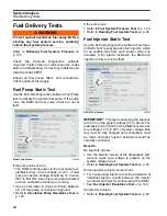
Page 321: ...ave not had training related to common shop safety practices you should do so not only to protect yourself but also to protect the people around you It is impossible for this manual to cover every potentially hazardous situation you may encoun ter However your understanding and adherence to the recommendations contained in this manual and use of good judgment when servicing outboards will help pro...

Page 322: ... IF NEUTRAL FORWARD REVERSE FORWARD or REVERSE propeller still powered turning unknown to operator or outboard will START in gear and boat will move suddenly boat will move opposite to direction wanted by operator How can loss of shift control be minimized When rigging or after servicing Read understand and follow manufacturer s instructions Follow warnings marked closely Assemble parts carefully ...

Page 323: ...EUTRAL Operator must be able to STOP propeller What could happen If Operator cannot slow down the outboard or shift into NEUTRAL gear stop propeller Operator could panic and lose control of boat How can loss of speed control be minimized When rigging or after servicing Read understand and follow manufacturer s instructions Follow warnings marked closely Assemble parts carefully Make adjustments ca...

Page 324: ...tarts here at the steering wheel and ends here at the trim tab on the outboard What could happen If steering system comes apart boat might turn suddenly and circle Persons thrown into the water could be hit If steering jams operator may not be able to avoid obstacles Operator could panic If steering is loose boat may weave while operator tries to steer a straight course With some rigs at high spee...

Page 325: ... that will not loosen rust or weaken Tilt outboard into boat then turn it transom mounted steerer stop to stop Be aware that raising or lowering outboard on transom can change a set up which was OK earlier If moved up or down even one half inch run test again to make sure steering parts are free and clear During this procedure steering parts Must not bind and Must not touch other boat outboard or ...

Page 326: ...nk What is most important Fuel leakage must be eliminated Stray electric sparks must be avoided What could happen When not boating fuel leaking in car trunk or van or place where portable tank is stored base ment or cottage could be ignited by any open flame or spark furnace pilot light etc When boating fuel leaking under the engine cover could be ignited by a damaged or deteriorated electrical pa...

Page 327: ...d Metal Clamps Tie Straps Position as shown in manual Screws Nuts Washers Tighten firmly these keep clamps in position and ends of wires from sparking Where lock washers are called for use them Spark Plug Boots Not torn or cracked Fully pushed onto spark plug Spark Plugs Avoid rough handling that could crack ceramic part of plug Sparks may jump across outside of plug All Connections Clean Tight Pr...

Page 328: ...Check for leaks under engine cover If tank cap has an air vent valve make sure it is closed Whenever possible remove hose from outboard and from tank Store hose around ears of tank This way gasoline is trapped in tank and not in the hose where it might leak onto the floor if the hose deteriorates If gasoline tank is stored indoors do not put it in a room having an appliance with a pilot light or w...

Page 329: ... must stay in position on boat s transom Outboard may S L I D E on transom Boat may turn and be hard to steer Outboard may T I L T on transom Boat may turn and be hard to steer If outboard hits something solid and does not stay on the transom boat occupants may be injured from the outboard or its parts entering the boat Boat s transom could break away Outboard may be lost overboard Boat may SINK T...

Page 330: ...ansom is curved outboard may come loose Mount on flat surface only Use shims to make surface flat Use bolts nuts and washers supplied with outboard They are usually special and will not rust or weaken Check for a high speed blow to the lower unit OR I was backing up and I think the outboard may have hit a tree or something Check for a slow heavy squash to the outboard Look for damaged parts and lo...

Page 331: ...ard must not trim in too far suddenly Boat may SINK At high speeds sudden trimming in too far may dive boat under water or spin it around Read understand and follow manufacturer s instructions Follow warnings marked closely Test your work whenever possible If oil leaks are seen in service areas determine source Keep reservoir filled If outboard is hydraulic tilt trim model always return rod to hol...

Page 332: ...here at the clip and lanyard and ends here in the ignition system on the powerhead What is most important The emergency stop system must STOP the engine when the clip is removed or the lanyard pulled from the emergency stop key switch If switch fails If lanyard is caught engine will keep running engine will keep running when clip is pulled from the switch ...

Page 333: ...tor may drown and boat WILL run into something How can failure of the emergency stop system be minimized When rigging or after servicing Read understand and follow manufacturer s instructions Follow warnings marked closely Assemble parts carefully Inspect lanyard for cuts or fraying clip for wear Replace with original parts Do not substitute Locate control box and other items in area to keep lanya...

Page 334: ...t proper safety takes time Reading and understanding instructions Re reading warnings marked Putting parts together correctly Making correct adjustments Testing your work And making sure Worn or damaged parts are replaced Replaced parts are like originals in every way Customer is told of things which need attention But do you really want the alternative ...

Page 335: ...f gravity Stand Clear It might hit you as it swings If engine does not have fixed lifting bracket and you use Universal Puller P N 378103 and Lifting Eye P N 321537 or Lifting Eye and Adapter Assembly P N 396748 use only the special hardened screws and washers from the set Outboard can drop suddenly if hoist or engine stand are in poor shape or too small for the job Make sure shop aids have extra ...

Page 336: ...uard to work on the outboard remember loose clothing open shirt sleeves neckties hair jewelry rings watches bracelets hands and arms can be caught by the spinning flywheel Handling high voltage parts like spark plugs and coils can shock you and may cause you to recoil into the rotating flywheel When you do things that turn the flywheel like Off season storage fogging oiling of outboard Removing pr...

Page 337: ...ons and other boats Avoid exhaust fumes from the engine or other boats provide proper ventilation shut off the engine when not needed and be aware of the risk of backdrafting and conditions that create CO accu mulation In high concentrations CO can be fatal within minutes Lower concentrations are just as lethal over long periods of time DANGER DO NOT run the engine indoors or without adequate vent...

Page 338: ...ing engine or operating boat Do not allow anyone near a propeller even when the engine is off Blades can be sharp and the propel ler can continue to turn even after the engine is off Always shut off the engine when near people in the water Eyes need protection when Grinding Spraying cleaners and paints Chiseling Tip When steel on steel use plastic or brass type hammers They don t chip off as easil...

Page 339: ...ity when connecting these larger leads 3 Always charge in a well ventilated area Charging causes acid solution to give off hydrogen gas through the vents in the caps Make sure vents are open If clogged pressure inside may build Battery may EXPLODE While charging or discharging remember No smoking No flames No sparks DO NOT check battery charge by placing metal objects across posts You will make sp...

Page 340: ...them if fumes are smelled Matches cigarettes blow torches welders Electric motors with unsealed cases Electric generators with unsealed cases Light switches Appliance pilot lights or electric ignitors furnace dryer water heaters Loose wires on running outboards Other variables which may ignite fumes How many of these are in your repair area 20 Parts Air By Volume 1 Part Gasoline Gas Fumes If the a...

Page 341: ...n hurt people READ How and where to use How to give First Aid Have recommended First Aid materials on hand should an emergency arise How to dispose of can It s all on the back of the can or bottle label And remember Little children are very curious and will try to taste everything so keep containers away from children ...

Page 342: ...erstand that the service manual as a whole and this Safety section in par ticular contain essential information to help prevent personal injury and damage to equipment and your customers 6 Have you received training related to common shop safety practices to protect your self and others around you 7 When replacement parts are required will you use Evinrude Johnson Genuine Parts or parts with equiv...

Page 343: ...m Ion Warning 27 Maintenance 27 28 Requirements 13 15 27 Storage 50 Bearing Connecting Rod 242 Crankshaft 237 238 Break In EMM Programming 174 250 Oiling 174 Procedure 70 C Cable Hose and Wire Routing 21 Capacitor Test 87 Connecting Rods Installation on Crankshaft 241 242 Installation on Piston 239 Orientation 242 Removal from Crankshaft 230 Control Cable Adjustments 22 Installation 22 Cooling Sys...

Page 344: ...179 Oiling Rate 70 175 Reports 72 Sensor Monitoring 96 Static Ignition Test 85 Timing Verification 71 116 TPS Calibration 71 116 Dual Outboard Alignment 32 I Command Settings 25 E Electrical Circuits EMM Pin Locations 93 Fuse 96 Ground Circuits 95 Key Switch 103 Start Circuit 102 SystemCheck 108 109 Electrical Connectors 125 AMP Connectors 126 Deutsch Connectors 125 Packard Connectors 129 Electric...

Page 345: ...ake Manifold 154 Minimum Octane 138 Pressure Tests 143 Priming 142 Relieving Pressure 147 Requirements 137 Troubleshooting 143 Vapor Separator 139 149 Fuse 96 G Gauges Tachometer 34 Trim Gauge Test 301 Gearcase Installation 46 Lubricant 39 Removal 45 Grommet 21 H Honing 233 Hoses Inspection 43 Oil Distribution 183 Oil Recirculation System 171 Routing Cooling System 190 191 Routing Fuel System 135 ...

Page 346: ... Trailering Bracket 38 Trim and Tilt 40 M Maintenance and Inspection Schedule 18 Midsection Stern Bracket Servicing 281 Tilt Tube Servicing 270 Models Included Models 11 Model Designation 10 Serial Number Location 10 Motor Mounts Lower Mount Servicing 272 273 279 Upper Mount Servicing 274 275 278 280 N Neutral Start Switch Tests 106 Neutral Switch 63 New Engines Outboard Rigging Procedure 20 O Oet...

Page 347: ...8 300 Remote Controls Cable Adjustment 22 Cable Installation 22 Rigging Outboard 20 RPM Limit 62 64 S S A F E Description 66 Oil Pressure 62 Temperature 59 61 Voltage 59 Sensors 96 Air Temperature Sensor 61 97 Barometric Pressure Sensor 60 Crankshaft Position Sensor 63 85 96 EMM 59 Engine Temperature Sensor 61 97 198 Exhaust Pressure Sensor 43 60 Knock sensor 64 98 Oil Pressure 62 169 Tests 96 Thr...

Page 348: ...inkage Installation 246 Lubrication 38 Removal 228 Throttle Position Sensor Calibration 116 Description 62 Resistance Test 97 Tilt Limit Switch Adjustment 30 Cam Installation 270 271 Tilt Support 289 Tilt Tube Installation 271 Lubrication 38 Removal 270 Timing Adjustments Timing Pointer 115 Timing Verification 116 TPS Calibration 116 Tools Ball Socket Remover tool P N 342226 154 Bootstrap Tool P N...

Page 349: ...ch P N 912084 308 312 315 316 Wrist Pin Cone P N 331913 240 Wrist Pin Pressing Tool P N 396747 231 Wrist Pin Retaining Ring Driver P N 396747 240 Torque Charts see Service Charts TPS Calibration 71 116 Trailering Bracket 289 Lubrication 38 Trim and Tilt Assembly 309 313 Circuits 108 Disassembly 305 312 Electrical Circuit Tests 108 Fluid 317 Inspection 296 Lubrication 40 Modes of Operation 290 Moto...

Page 350: ...Installation 149 Removal 149 Voltage Drop Test 104 W Water Intake Screens 35 Inspection 35 Water Pressure Gauge 26 Water Pump Description 192 Water Supply Tube 192 Winterizing 48 Wiring Harness Connections 24 Wrist Pin Installation 239 Removal 231 ...

Page 351: ...10 A Check wiring then replace faulty fuse Wiring harness Check for 12 V at terminal B of key switch Key switch Check key switch operation Starter solenoid Check wiring and test solenoid Starter or bendix drive gears Check starter inspect bendix drive gears Seized powerhead or gearcaseCheck and repair as needed Outboard turns slowly Discharged battery Check battery recharge or replace Battery cabl...

Page 352: ...g Check voltage at injectors Excessive fuel or oil engine flooded Check for leaking injectors leaking fuel or oil lift pump or leaking vapor separator vent refer to System Analysis Low or no 55 V alternator out put Check voltage on 55 V circuit refer to System Analysis and Electrical and Ignition Capacitor or 55 V circuit wiring Check capacitor and 55 V circuits refer to Sys tem Analysis and Elect...

Page 353: ...anti siphon valve and fuel pick up check for fuel system air leaks Low or no alternator output 55 V Check voltage on 55 V circuit refer to System Analysis and Electrical and Ignition Capacitor or 55 V circuit wiring Check capacitor and 55 V circuit white red refer to System Analysis and Electrical and Ignition Restricted or leaking fuel injec tor s Check injectors refer to Fuel System Weak or erra...

Page 354: ...t 55 V Check voltage on 55 V circuits refer to System Analysis and Electrical and Ignition Capacitor or 55 V circuit wiring Check capacitor and 55 V circuit refer to System Analysis and Electrical and Ignition Contaminated or poor fuel quality Check or replace fuel supply Low fuel pressure Check pressure refer to Fuel System Air in fuel system Check for air in fuel supply manifold refer to Fuel Sy...

Page 355: ...tion Check ignition refer to System Analysis and Electrical and Ignition Fuel injector electrical circuit or control function Check voltage at injectors refer to System Anal ysis Restricted or leaking fuel injec tors Check injectors refer to Fuel System Low fuel pressure Check circulation pump operation refer to Fuel System EMM programming timing or operation Check EMM program and timing check inj...

Page 356: ... air leaks Restricted or leaking fuel injec tor s Check injectors refer to Fuel System Faulty wiring connections grounds or CPS air gap Check all grounds connections and wiring Check CPS air gap Low alternator output 55 V Check voltage on 55 V circuit refer to System Analysis and Electrical and Ignition EMM program timing or oper ation Check EMM program and timing check injector coefficients and m...

Reviews: