background image

Summary of Contents for 1026

Page 1: ...electronic solid state instrument generating sinusoidal or narrow band random outputs for controlling vibration exciters in a frequency range 1 Hz to 10 000 Hz Built in are two independent vibration meters with slave filters an 80 dB dynamic range compressor amplifier interlocking and trip facilities ...

Page 2: ......

Page 3: ...EXCITER CONTROL TYPE 1026 February 1972 ...

Page 4: ......

Page 5: ...justment 32 3 2 Operation as a Vibration Meter 32 Mounting the Accelerometer 33 Preamplifier 34 Vibration Meter Mode and Level 34 Meter Rectifier Selection 36 Effective Averaging Time 36 Set up Control 36 Summary 37 3 3 Operation as a Signal Generator 37 With no Compressor Loop 38 With Compressor Loop controlling the Output Voltage 39 3 4 Operation as a Vibration Exciter Control Sinusoidal Output ...

Page 6: ...2 1 MHz Oscillator 62 Narrow Band Random 62 4 2 Main Output 63 4 3 Frequency Readouts 64 Digital Outputs 64 Analogue Readout 65 DC o f 65 DC ex log f 65 4 4 Tuning Outputs 65 1 2 MHz and 1 2 1 MHz 65 60 kHz and 60 50 kHz 65 100kHz and 100 110kHz 66 Constant Level Outputs 66 4 5 Sweep Control 66 4 6 Compressor 68 Compressor Speed 69 Compressor Control 71 4 7 Safety Limits and Interlock 71 Safety Li...

Page 7: ...Cross Over Specifications Three Modes 91 7 REMOTE CONTROL 92 7 1 Start Stop Reverse of Frequency Scan 92 7 2 External Voltage Controlled Sweep 92 7 3 Phase Control of Output Voltage 92 7 4 Compressor 93 External AC Compressor Control Signal 93 External Unsmoothed DC Compressor Control Signal 94 External Smoothed DC Compressor Control Signal 95 7 5 Protection Circuitry 95 Remotely set to Stand By 9...

Page 8: ...102 DC ex log f 102 Constant Level Outputs 102 9 2 Digital Outputs 103 Digital Coded Frequency Output 103 Bandwidth Control 104 10 APPENDIX 106 11 SPECIFICATIONS 108 11 1 Generator Section 108 11 2 Vibration Meter Section 111 11 3 Compressor Section 112 11 4 General 113 ...

Page 9: ...peed The compressor speed can be set to be continuously variable with frequency thus optimizing the stability and distortion conditions The signal supplied to the compressor speed circuitry can be selected to be wide band RMS rectified wide band average rectified or narrow band average rectified Internal slave filters can be switched into the vibration meters This gives considerable assistance whe...

Page 10: ...curate sweep speeds These can be arranged to match the paper speeds of the Level Recorder retaining the calibration of the paper in use The Level Recorder Type 2307 has voltage steered paper speeds and this can be driven from a rear panel output of the 1026 Full remote control is possible of sweep functions interlock phase and compressor amplifier The removal of rear panel and circuit board short ...

Page 11: ...26 Single pole single throw switch used to apply mains power to the instrument When switched On the digital read out of frequency and the meter scales are illuminated A five position switch allowing the fre quency sweep Upper Limit and Lower Limit to be set up The requir ed vibration Level on the table can be 9 ...

Page 12: ...wise click position The remainder of the controls can most conveniently be grouped under three function headings 2 1 1 Generator Section GENERATOR FUNCTION FREQUENCY DISPLAY Digital FREQUENCY DISPLAY Analogue 10 A five position switch selecting either a 1 10 000 Hz Sine or a Rayleigh distributed Narrow Band Random output signal The Narrow Band Ran dom output can have a 3 dB spec tral width of 3 16...

Page 13: ... commence in the frequency increasing direction up unless commencing from the upper limit of the sweep At any point during a sweep either going up or down in fre quency the sweep direction can be re versed by the Reverse button The sweeping is halted by the Stop but ton Two indicator lamps showing the direction of the frequency sweep The Up lamp is lit for increasing frequen cy and the Down lamp i...

Page 14: ...ct sweep speed within that range is set up by the SWEEP RATE potentiometer The SWEEP RATE is a ten turn calibrated potentiometer giving con tinuous adjustment The SWEEP RATE RANGE can select one of four linear sweep ranges or one of three logarithmic ranges The linear ranges are 1 10 10 100 100 1000 and 1000 10 000 Hz min The maximum fre quency sweep available in the 1 10 Hz min range is from 1 20...

Page 15: ...s the amplifier in the vibration meter section is overloaded and that the input range must be increased by changing the LEVEL switch The vibration meters can measure or control different input functions select able by the MODE switch The meters are calibrated for input acceleration signals normalized to 10 mV g Accel The vibration meter is used as a direct measuring amplifier indicating the value ...

Page 16: ...ol consists of a multi position switch and a coaxially mounted potentiometer The switch works in conjunction with the MODE control When Accel or Vel is selected on the MODE switch the LEVEL control can select a Full Scale Deflection of II 1tr 1 3 1 II 10 1 30 1 II 100 1 300 1 or 1 000 g or inches sec When Displ or Accel Grad is selected the LEVEL control can select a FSD of 0 01 1 0 03 1 0 1 1 0 3...

Page 17: ...in one of the Narrow Band Random positions the meter is calibrated to read RMS The meter rectifier not meter calibration which is always as above is selectable by three push buttons RMS Average Track A true RMS wide band rectifier is select ed as the meter rectifier Selects a rectifier that will give the aver age value of the input signal Connects a bandpass filter whose centre frequency is slaved...

Page 18: ...ressor control is chosen by the buttons to the left of the row and Channel B rectifier control is selected by those to the right A five position switch used to select the slope of the continuously variable com pressor speed The available slopes are 0 1 0 3 1 3 and od dB second per Hz A switch to select the maximum com pressor speed or to switch off the com pressor and have an unregulated genera to...

Page 19: ...an be 1 3 or 6 dB If the safety circuit is triggered the generator auto matically switches back to Stand by and the STAND BY lamp is lit The safety circuit is switched off when the SAFETY LIMITS switch is at Off When the safety circuit is operative the SAFETY CONTROL IN lamp is lit Ground Fig 2 2 Rear panel of 1026 MAINS VOLTAGE SELECTOR and CARTRIDGE FUSE The generator can be set to operate on 10...

Page 20: ...narrow band random outputs to external loads The frequen cy range available is from 1 10 000 Hz at levels between 0 3 V RMS The maximum load is 10 kD shunted by 3 nF An isolated BNC connector similar to the LINEAR connector except with a high pass filter in series A simple RC filter is used 1 nF 22 kD f3 dB 45 Hz See also section 4 2 This gives inherent matching to shaker low fre quency characteri...

Page 21: ...ose centre connection is a voltage varying as the logarithm of frequency between 0 and 6 V DC as frequency increases This output can be loaded by a 10 k Q load The middle output is 6 V as required by the Vibration Programmer Type 4411 The outer connection is the screen DC Output 6 v DC Output a log f 0 to 6V as frequency increases 27119 NOTE The following socket diagrams are external views of the ...

Page 22: ... Hz and fgen generated frequency The following sockets are also associated with the Generator section BANDWIDTH CONTROL 30 Hz 300 Hz 3000 Hz 20 A seven pin socket giving six output sig nals at certain frequencies Each output is derived from a Transistor Transistor Logic TTL gate and has two levels Logic 1 which lies between 2 4 and 5 V and Logic 0 which lies between 0 and 0 4 V This socket is prim...

Page 23: ...l Sweep Signals are to be connected to this pin after removing the shorting link between Pin 2 and Pin 5 The input impedance at this pin is approx 50 kQ and the voltage range for full frequency deviation 1 10 000 Hz is 0 75 8 25 V thus the slope is 0 75 mV Hz 1 2 1 MHz Osc DC ex f via a DC Amplifier From Manual Control or 1 Ramp Generator Reverse Pin 6 Short circuiting this pin to refer ence will ...

Page 24: ...tch con necting one or the other of them to reference The internal shorting link between Pin 3 and Pin 4 must first be removed Pin 4 Internally connected to signal reference The plug used with this socket is a Cannon Type WK A7 21C B K Part No JP 0700 Two BNC isolated sockets used in Master Slave operation They are internally linked by a short circuit When this is removed the top socket supplies a...

Page 25: ...ency from 1 2 MHz for generator output frequen cy 1 Hz to 1 0 MHz for generator out put frequency 10 000 Hz The bottom socket becomes available to take a similar signal 1 2 1 MHz from an other generator Thus any generator can be used either as a Master or as a Slave The output impedance of the upper socket is 75 n Signal Ground Signal Ground A BNC isolated socket providing a symmetrical square wav...

Page 26: ...oaded by a 10 kQ load A BNC isolated socket providing a symmetrical square wave output whose prf varies between 60kHz for genera tor output frequency of 1 Hz and 50 kHz for generator output frequency of 10 000 Hz The output voltage is between 2 4 and 5 0 V peak to peak and the socket load capability is 5 kQ shunt ed by 150 pF A seven pin socket at which external control of both output phase and co...

Page 27: ...haracteristic is shown in Fig 4 6 relating the voltage at Pin 7 to the associated amount of com pression The plug used with this socket is a Cannon Type WK A7 21C B K Part No JP 0700 CHANNEL SELECTOR SWITCH A three position slide switch and two BNC isolated sockets used to route the and INPUT SOCKETS signals to be measured to the appropri ate amplifiers Channel Selector With the CHANNEL SELECTOR s...

Page 28: ...annel will be discussed EXT FILTER 26 From Input via MODE Ext Filter A seven pin socket t which any exter nal filters that may be required are con nected into the vibration meter Pin 2 connects the signal at the INPUT sockets as chosen by the CHANNEL SELECTOR switch to the input of an external filter when the MODE switch is at Ext Filter or 6 dB Oct The screening of the input to the external filte...

Page 29: ... uncal ibrated Pin 3 For use with the Vibration Programmer Type 4413 remove the shorting link between Pin 1 and Pin 3 Connect the input of the 4413 to Pin 1 and the output to Pin 3 The plug used with this socket is a Cannon Type WK A7 21C B K Part No JP 0700 A seven pin socket used to connect an external vibration meter Pin 1 Connect an external recorder to this pin Screen on Pin 4 Pin 2 Connect t...

Page 30: ...e still operable allowing the meter and compressor to operate on RMS Average or Track using the externally connect ed tracking filter Only low insertion loss filters can be inserted at this point The input at Pin 6 for full scale deflec tion is 1 V RMS Pin 4 is connected to SIGNAL GROUND and can be used as an earth point for cable screen The pi ug associated with this socket is a Cannon Type WK A7...

Page 31: ... be monitored at this pin Pin 7 is connected to the SIGNAL GROUND The two resistors and the shorting link are used when an external vibration meter is connected to the EXT VIB METER socket The plug associated with this socket is a Cannon Type WK A7 21C B K Part No JP 0700 A seven pin socket giving access to the compressor amplifier and is designed for use with external vibration program ming equip...

Page 32: ...ull dynamic range of the compressor is available for an input signal of 1 V average Pin 4 is connected to SIGNAL GROUND Pin 3 and Pin 7 provide a voltage divi sion when using an external program mer The plug associated with this socket is a Cannon Type WK A7 21C B K Part No JP 0700 See description in the Generator Sec tion 2 2 1 A seven pin socket giving remote con trol over the interlock and safe...

Page 33: ...cts connected between these pins Pin 4 is connected to SIGNAL GROUND Pin 6 is connected to a 15 V supply via a 500 n series resistor Pin 5 and Pin 6 The Safety Lim its circuitry for Channel A can be remotely inhibited by closing a normally open pair of contacts connected between these pins Pin 3 and Pin 6 The Safety Limits circuitry for Channel 8 can be remotely inhibited by closing a normally ope...

Page 34: ...heck that the voltage selector corresponds to the available mains voltages Switch POWER On The digital counter the scale lamps and the Stand By lamp will now light 3 2 OPERATION AS A VIBRATION METER The Exciter Control Type 1026 has two independent vibration meters These can be used to measure any vibratory object but the primary inten tion is that one channel would be used to control the feedback...

Page 35: ...veraging Time Mode Level Fig 3 1 Setting up the Vibration Meter section 3 2 1 Mounting the accelerometer Piezoelectric accelerometers although rugged and dependable require that they be carefully fixed to the test specimen Care and attention to the mounting methods will reduce the attendant changes in accelerometer frequency response The instruction manual supplied with 8 K Acceler ometers covers ...

Page 36: ... can be chosen as the measuring channel If one channel is in use as the acceleration control channel for a vibration exciter the acceleration velocity or displacement of the control point can be read off on the other channel by switching the CHANNEL SELECTOR switch such that the single control input is fed to both vibration meters For independent operation of each channel select the centre positio...

Page 37: ...g large lettering Centimetre em calibration using small lettering and Acceleration Gradient calibrated in gJSiC using large lettering Full scale deflections are 0 01 0 03 0 1 0 3 1 3 and 10 The other semi circle covers Acceleration calibrated in g using large lettering and Velocity inches sec calibration in large lettering centimetre second em sec calibration in small lettering with available FSDs...

Page 38: ...th is also 10Hz etc These AC signals can also be obtained at the relevant pins of the EXT VIB METER socket see section 2 2 2 for use with a Level Recorder or other external monitor Note that these signals are 60kHz Sine or Narrow Band Random centred on 60 kHz RMS and Average push button switches choose between a true RMS rectifier and an average value rectifier 3 2 5 Effective Averaging Time The o...

Page 39: ...nitoring instrument or a Level Recorder the broad band AC outputs on the applied Track output 60kHz to the meter rectifier can be obtained at the rear panel EXT VIB METER socket See section 2 2 2 Note a The meter calibration changes with GENERATOR FUNCTION selected as printed on the meter scales b The internal slave filters selected in position Track change with GENERATOR FUNCTION as shown in sect...

Page 40: ...oop Connect the 1026 as shown in Fig 3 2 but without the accelerometer and preamplifier Set 38 Exciter Body 4801 Power Amplifier 2707 Conditioning Amplifier 2626 Exciter Control 1026 270 1 Fig 3 2 Set up for a Vibration Test OUTPUT VOLTAGE to GENERATOR FUNCTION SAFETY LIMIT MAX COMP SPEED SWEEP CONTROL see Sweep Control section 3 6 Fully anticlockwise position click off Sine or Narrow Band Random ...

Page 41: ...lock wise the OUTPUT VOLTAGE control The two vibration meters can be used as Voltmeters Conversion factor 10 mV g input Impedance 47 kr 2 For use in this way the MODE switch should be in Accel and the LEVEL switch used to select the range of operation Choose suitable EFFECTIVE AVERAGING TIMES and meter rectifier operation RMS Track or Average Note that since the GENERATOR FUNCTION switch changes t...

Page 42: ...VERAGING TIME As required RMS TRACK or AVERAGE As required SET UP CONTROL Operate The output voltage from the 1026 at any frequency will now be as characterized by the setting of the MODE and LEVEL controls of the selected control channel 3 4 OPERATION AS A VIBRATION EXCITER CONTROL SINUSOIDAL OUTPUT A typical exciter system is shown in Fig 3 2 and this will be used to explain the basic operation ...

Page 43: ...inder of the sweep set up details are given in section 3 6 3 4 2 Vibration Meter Section At least one of the built in vibration meters must be reserved as a control channel as selected by the COMPRESSOR CONTROL A B or Larger also see section 3 4 3 a Control Channel Connect the output from the Conditioning Amplifier to either of the INPUT sockets and use the CHANNEL SELECTOR switch to route that IN...

Page 44: ...r must be set up independently Thus when setting Level choose the vibration meter being pre set as COMPRESSOR CONTROL set up the control level as above and finally return COMPRESSOR CONTROL to Larger Also ensure that the rear panel CHANNEL SELECTOR switch routes the control signal to both metering channels b Monitor Channel If only one of the meters has been chosen as a Control Channel the other m...

Page 45: ...OR CONTROL push button switches The output supplied to the compressor rectifier from each vibration channel is chosen independently thus when COMPRESSOR CONTROL is by the Larger of the vibration signals the appropriate RMS Track or Average push button associated with each channel must be selected When either A or B is selected only the appropriate RMS Track or Average button associated with the ch...

Page 46: ...the chosen com pressor speed can control Otherwise the safety control will switch the system to Stand By During testing alteration of any of the switches shown in Fig 3 3 would cause a step or transient change in the exciter vibration level and these switches are therefore interlocked electrically Alteration of any interlocked switch will automatically put the 1026 into the Stand By mode thus supp...

Page 47: ...Stand By and back to Operate again The Exciter Control should be returned to Stand By manually if test ing is temporarily halted for repairs to the test specimen etc At the end of a test the generator should be returned to Stand By before the POWER is switched Off 3 4 5 Summary Connect the control and monitor signals normalized to 10 mV g to the INPUT sockets and route them to the appropriate chan...

Page 48: ... Repeat For setting of SWEEP RATE and sweep limits see section 3 6 To set Vibration Level Set COMPRESSOR CONTROL to MODE LEVEL switch RMS TRACK or AVERAGE SET UP CONTROL LEVEL Potentiometer SET UP CONTROL COMPRESSOR CONTROL To set Compressor Section Set 46 MAX COMP SPEED and COMP RATE A B RMS Track or Average Required vibration mode Required vibration range Level Until the required control point v...

Page 49: ...Operate To suspend testing for a short time return the SET UP CONTROL to Stand By Recommence by switching back to Operate To terminate a test switch SET UP CONTROL to Stand By Ensure that the Power Amplifier Gain is fully reduced and that the whole system is left in a condition that will not cause transients at the next switch on 3 5 OPERATION AS A VIBRATION EXCITER CONTROL NARROWBAND RANDOM Narro...

Page 50: ...CHANNEL SELECTOR switch to route that INPUT socket to the chosen Control Channel Set COMPRESSOR CONTROL to A B or Larger OUTPUT VOLTAGE Fully clockwise SET UP CONTROL Level EFFECTIVE AVERAGING TIME As required Then on the Control Channel Set RMS TRACK or AVERAGE As required For Narrow Band Random outputs the slave filters have constant band widths The 3 dB bandwidth is the same as that of the nois...

Page 51: ...sonant response at lower frequen cies At a certain frequency determined by noise bandwidth resonance 0 etc the specimen response to a sweep random excitation is approximately the same as the response to a wide band response Thus the sweep test should be modified so that below this frequency the specimen is constant Acceleration excited but above the frequency it is excited by a signal of a constan...

Page 52: ...ack or Average As required say Accel Grad Relevant range Adjust until required control point vibration level is shown on Channel B meter Finally return the SET UP CONTROL to Stand By and select COM PRESSOR CONTROL Larger 3 5 3 Compressor Section a Regulation Speed The Compressor is controlled by the COMP RATE and MAX COMP SPEED controls These two controls are interdependent and give resultant comp...

Page 53: ...le 3 1 Maximum Compressor Speed for a given noise bandwidth b Compressor Control Signal Set COMPRESSOR CONTROL A B or Larger RMS Track or Average Remember that the interlocking system requires that a compressor rectifier must be chosen for both channels even though only one of them is used as control channel c Swept Narrow Band testing Set GENERATOR FUNCTION to SWEEP CONTROL see sec 3 6 3 5 4 Oper...

Page 54: ... within the range chosen by the MODE and LEVEL switches LEVEL changes should be made slowly enough to retain full compressor control During testing alteration of any of the switches shown in Fig 3 3 would cause a step or transient change in the exciter vibration level and these switches are therefore interlocked electrically Alteration of any interlocked switch will automatically put the 1026 into...

Page 55: ...requency Set GENERATOR FUNCTION to Narrow Band Random of re quired bandwidth SWEEP CONTROL Manual Single or Repeat Automatic sweep modes are set up as for sweeping sine tests see Section 3 6 MANUALFREQUENCYCONTROL and associated VERNIER Until required noise band mid band frequency is set on the Digital display or on the analogue meter To set Vibration Level Set COMPRESSOR CONTROL to MODE LEVEL swi...

Page 56: ...MAX COMP SPEED Adjust LEVEL potentiometer MANUAL FREQUENCY CONTROL to adjust noise band centre frequency in SWEEP CONTROL Manual or the starting frequency in SWEEP CONTROL Single or Repeat Use the Start Stop and Reverse buttons as required by sweep conditions Moving any interlocked switch will set the 1026 to Stand By To restore operation switch the SET UP CONTROL from Operate to Stand By and back...

Page 57: ... By if any attempt is made to switch from an automatic sweep mode to manual or vice versa when in position Operate Further the output frequency at the time the button is pressed will be held until the 1026 is set to Level using the SET UP CONTROL If the starting frequency is set at the upper or the lower limit the sweep will commence from the relevant limit and in the relevant direction Set SWEEP ...

Page 58: ...0 000 Table 3 2 Sweep Rate ranges The frequency sweep has three pre set points a the Upper Limit frequency b the Lower Limit frequency c the starting frequency To set up a Upper Limit b Lower Limit c Starting Frequency SET UP CONTROL to Upper Limit Adjust UPPER LIM IT for re quired frequency shown on read outs SET UP CONTROL to Lower Limit Adjust LOWER LIMIT for re quired frequency shown on read o...

Page 59: ...ould this happen the sweep will stop At the end of each Single sweep the Exciter Control is electronically returned to Stand By condition To return the 1026 to normal operation the SET UP CONTROL must be switched from Operate to Stand By and back to Operate The fre quency at which the trip occured will be held throughout and using the Start button will allow the test to be continued from the frequ...

Page 60: ...witch LEVEL switch and LEVEL potentiometer Preset required COMP RATE and MAX COMP SPEED Set SAFETY LIMITS to SET UP CONTROL to As required Operate Wait for the pre set output level to be established by the compressor action 58 Commence sweeping using the Start button Reverse the sweep direction with the Reverse button Stop sweeping with the Stop button In the event of a trip into Stand By to recom...

Page 61: ... test cease testing by switching the SET UP CONTROL to Stand By before switching off mains power to the test system Ensure that the system is left in a condition that will not cause transients at the next switch on 59 ...

Page 62: ...uency components in its output equal to the sum and difference of the two input frequencies The difference component is filtered amplified and made available as the output signal The inputs to the mixer are at 60kHz and between 60 and 50 kHz See Fig 4 2 A r Inputs B i t 1 I I Tuning Outputs Voltage Controlled Rectifier Compressor Control Sweep Control Modulator and LP Filter Amplifier Main Output ...

Page 63: ... __ Sweep Control Voltage Es Output from AC Level Potentiometer X 61 60 Compressor Rectifier fv 1 2 MHz Compressor Speed V 60 kHz E DC Fig 4 2 Stabilization of the variable oscillator High 22k 1 2TII 16 ...

Page 64: ... value of generated frequency depends on the DC voltage across it A varactor diode has a voltage dependent capaci tance and thus when used in a tuned circuit the resonant frequency of the circuit is voltage controlled Frequency counting is carried out directly on the high frequency 1 2 1 MHz signal This enables the sampling time in the counter circuitry to be as short as 0 5 sec for 0 1 Hz reading...

Page 65: ...om signal is obtained by mixing of the variable 60 50 kHz sinusoidal oscillator with either the fixed 60kHz sinusoidal or the 60 kHz narrow band random noise signal The fixed frequency signal is controlled in level by the compressor circuit see section 4 6 The mixing process is performed in a double balanced ring modulator and the difference signal is obtained by filtering The resultant signal is ...

Page 66: ...f 0 5 sec a short enable pulse transfers the decade of each decade counter via the driver stages to the relevant numeral of the digital readout tube After transfer a reset pulse clears the counters for the next read in period 1 2 MHz Bandwidth Control Socket Digital Readout Bandwidth Control Logic Fig 4 4 Digital Frequency Output A BCD coding of the generated frequency is supplied from the counter...

Page 67: ...frequency in the range 0 to 6 V DC 4 4 TUNING OUTPUT 4 4 1 1 2 MHz and 1 2 1 MHz These are derived directly from the master oscillator and the variable oscillator 4 4 2 60 kHz and 60 50 kHz The 3 V peak to peak sine wave 60 kHz signal is derived from the 1 2 MHz oscillator by a division process x 1 20 Frequency division is realized by firstly deriving a suitable level square wave from a saturated ...

Page 68: ...onic component is tuned 4 4 4 Constant Level Outputs The symmetrical square wave signal at 240 200kHz x 1 5 of the 1 2 MHz master oscillator is fed to a logic system In phase and goo phase shifted square waves at 60 50kHz are obtained and after modulation with a 60kHz constant amplitude signal 1 20 of the 1 2 MHz master oscillator suitable filtering and amplification results in two sine wave outpu...

Page 69: ...ange the sweep rate is set by continuous adjust ment of V0 The sweep control circuitry provides interlocking between the position settings of the Repeat Single and Manual push buttons of the SWEEP CONTROL and the settings of the MANUAL F REOUENCY CONTROL UPPER LIMIT and LOWER LIMIT controls to prevent illogical conditions occuring For example the MANUAL FREQUENCY CONTROL cannot be used to set freq...

Page 70: ...plitude of the 60kHz signal prior to the modulator A three stage amplifier with FET controlled feedback is used to shift the phase of the 60kHz signal by the front panel PHASE control over a range greater than 360 The output of the phase shift amplifier is applied to basically a two stage amplifier again with FETs in the feedback loop The compressor control voltage is applied to each of these FETs...

Page 71: ...s unity K Constant In this case K 40 which corresponds to a regulation accuracy of 20 dB compressed to 0 5 dB Fig 4 6 4 6 1 Compressor Speed Basically this is controlled by an RC smoothing circuit and the constant 1000 dB sec 300 300 dB sec C Ql Ql 100 0 0 I 30 dB sec e 30 Q 0 0 E 0 u u Ql 10 dB sec 10 aJ 0 8 3 3 dB sec 1 dB sec 0 3 0 1 1 Hz 10 100 1 kHz 10 Frequency 27 20 Fig 4 7 Compressor Speed...

Page 72: ...Jand 1 dB sec 90 0 5Hz 1 2 5 10 20 50 100 200 500 1kHz 2 5 10 Frequency zr 9T 0 r r r dB 10 Camp Rate 1 3 dB sec per Hz 70 20 t 1 11 1 dB sec per Hz Ill 0 3 dB sec per Hz o 30 l l P _____ 3oor 1 1V 0 1 dB sec per Hz 5 2 c 0 CQ I 40 50 60 0 1 70 80 0 01 90 0 5 Hz 1 2 5 10 20 50 100 200 500 1kHz 2 Frequency Fig 4 8 Harmonic Distortion of 1026 a Second Harmonic b Third Harmonic 5 10 ...

Page 73: ...6 2 Compressor Control The switching that selects which channel is the control channel and which rectifier is used to produce the compressor control signal is done in these circuits The Larger selection is also done here The signal level from each vibration meter is fed into a comparator the output of which energizes the relevant FET gate allowing the larger of the two inputs to define the compres...

Page 74: ...side the window Using this system the number of periods between the trip initiation and output suppression is constant and independent of frequency The photograph of Fig 4 1 0 shows the change in output voltage of the 1026 when the trip is initiated In this case compressor control was lost because of a broken accelerometer cable The upper waveform indicates the time of the break and the lower show...

Page 75: ...ONTROL Operate the inhibit circuitry is initiated Logic circuitry is also included in the interlock system so that all controls are correctly inter related 4 8 VIBRATION METERS The vibration meters are identical and can operate independently A block diagram of one of the meters is shown in Fig 4 11 The Channel Selector routes the control signal to the relevant channel The normalizing factor used i...

Page 76: ... 3 Inches 0 1 g Jsec 0 1 0 03 0 03 0 01 0 01 1Hz 10 100 1kHz 10 1Hz 10 100 Frequency Fig 4 12 Useable ranges of Vibration Meter 4 8 1 Input Attenuator and Mode 1kHz 10 Frequency 1kHz 10 Frequency 2 71 1 17 The adjustment of the overall system gain is done by the input attenuator LEVEL Signal integration and processing is done in the MODE circuitry giving 6 dB oct 12 dB oct and 3 dB oct for Velocit...

Page 77: ... when working at reasonably high frequencies The filter used is an active Salien Key type with FET switching of the resistors controlling the filter response dB 0 4 8 c 0 ro 12 1 c 16 20 24 28 0 01 0 1 Frequency 271107 A Fig 4 13 Vibration Meter dynamic filter 4 8 3 Slave Filter The slave filter selected by the push button TRACK is shown in the block diagram of Fig 4 14 The low frequency input sig...

Page 78: ...ecomes twice the low frequency cut off of the low pass filter e g for a low pass cut off frequency of 1 5 Hz the transformed band pass filter would be 3 0 Hz To obtain constant bandwidth band pass filters therefore it is only necessary to change the value of the resistor in the low pass filter to accord with the required band pass bandwidth In the case of a constant percentage bandwidth band pass ...

Page 79: ...ge of the vibration meters has to be handled by these rectifiers They thus need a wide dynamic range The output of the slave filter at 60kHz is applied to the average rectifier since at this frequency a wide dynamic range RMS rectifier is not feasible However for the purposes of compressor control it is unimportant whether the rectifier is average or RMS so long as the signal is free from distorti...

Page 80: ...on levels at various parts of the test specimen 5 1 LEVEL RECORDER TYPE 2305 5 1 1 Synchronization No direct mechanical or electrical link is used between the 2305 and the 1026 The X plane shift of the 2305 is provided by a synchronous motor rotating at a speed dependent on the mains frequency driving through precision gearing This ensures a paper speed that is both defined and constant within a f...

Page 81: ...y When using calibrated Level Recorder papers QP 1124 QP 0124 QP 1152 QP 0424 QP 1142 and QP 1143 the range of available sweep speeds that give calibration factors Octaves mm the same as that of the paper are limited because Paper Speed mm sec is not a continuously variable function Suitable values are given in Table 5 1 The paper type QP 1130 cannot be used Sweep Speed Octaves min Paper Speed mm ...

Page 82: ...be used Choose a suitable sweep speed combination of SWEEP RATE RANGE and SWEEP RATE dependent on system Os slave filter bandwidths etc Also choose the compressor speed accordingly combination of COMP RATE and MAX COMP SPEED Set the start frequency as required On the 2305 Set up as in the Instruction Manual for Single Chart Recording Using the finger wheel set the chart so that the pen lies on the...

Page 83: ...rections by an external DC voltage Thus the X axis can be made to represent any quantity When used with the 1026 and controlled in the X axis by the output DC ex log f the use of two controls on the 2307 enables the two instruments to be synchronized to any calibrated recorder paper required 5 2 2 Recording To use the 1026 2307 combination each instrument must be set up separately for sweep speeds...

Page 84: ...nge Potentio meter fitted RECTI Fl ER RESPONSE As required LOWER LIMITING FREQUENCY As required WRITING SPEED As required PAPER DRIVE X Rec PAPER SPEED Select mm sec or em sec INPUT POTENTIOMETER INPUT ATTENUATOR PEN DRIVE between 0 0003 to 1 0 not 100 em sec As required As required On 3 Set the 1026 SET UP CONTROL Stand By and SWEEP CONTROL Manual for this adjustment only to the minimum ...

Page 85: ...side mounted screwdriver control Sensitivity of the 2307 to set the paper and pen coincident over the maximum analysis frequency 5 Fine adjust the synchronization by checking Zero as in 3 above and Sensitivity as in 4 above once more The Exciter Control Level Recorder combination is now synchronized for the analysis range chosen To operate return the 1026 to Single sweep and to the required Start ...

Page 86: ...e or more cross over points can be defined Cl 40 c 0 20 Q Qj J J 10 8 6 4 2 1 0 8 0 6 0 4 0 2 0 1 84 Predicted Envelope 60 Cont Line Derived Test Envelope 0 Measured Data Points 0 c 9n f I 10 15 g V1 td 0 8 0 t Lo Ll9Lcl_i _ _Q I 0 _l lli I JE o 8 0 o o0 l5g Jl_k1 1 c 0 010 v VI t t j os I 8go c u 8 v oa I n b 1 0 C lo r 0 r 7 c c 0 0 0 I o a I j t1 A t c 0 l if I I I d I v I I ll I I I I I I I I ...

Page 87: ...se are the most common specifications and can be simply implemented using the Larger function of the COMPRESSOR CONTROL Consider an exciter table controlled by one of the vibration meters at constant Displacement As frequency increases the table Acceleration level increases Acceleration a w 2 x Displacement If the other channel is set for an arbitrary Acceleration level and the Larger COMPRESSOR C...

Page 88: ...tronically switched series of level controls see Fig 6 3 It uses the DC a f output of the 1026 balanced against a DC value set in by the CROSS OVER FREQUENCY control of the 4413 At balance cross over point the channel selector switches to the next Level Potentiometer and the vibration level at the table changes accordingly To cover large charges of specified level attenuators have been fitted in s...

Page 89: ..._______________________________ J Vibration Programmer Type 5660 DC ex f 1 _ Channel A 1 _ Channel B Interlock 1 _ Compressor Signal 1 _ External Filter Channel A External Filter Channel B Fig 6 3 Principle of Type 4413 Vibration Programmer Generator Section 1 Compressor Section 1 Vibration Meter Section Exciter Control Type 1026 271167 ...

Page 90: ... it is supplied with channels 1 and 3 and channels 2 and 4 commoned Imple mentation would otherwise have required external junction boxes and extra cables All switches of the 4413 are included in the interlock system of the 1026 6 3 1 Interconnections 88 1 Remove the shorting links from the 1026 sockets METER AC COMP AC EXT FILTER REMOTE COMP CONT q BNC Pin 1 to Pin 2 Pin 1 to Pin 3 Pin 1 to Pin 2...

Page 91: ... Control I I Vibration 1026 I IProgrammer I I 4413 I 1 I Meter AC Level Camp AC 1 and 3 Channel A I 0 I Ext Filter Sens1t1v1ty 1 and 3 I G I Meter AC Level Camp AC 2 and 4 Channel B I 4 I Ext Filter Sensitivity 2 and 4 I 5 I Remote Interlock Camp Cont I 6 I DC a f 9Cross Over Frequency I I 2 TIL I Fig 6 5 Interconnection of 1026 and 4413 6 3 2 Operation 1 Set up the Generator and Compressor sectio...

Page 92: ...bration mode 7 Set the required vibration level using the LEVEL switch of the 1026 and the VIBRATION LEVEL potentiometers of the 4413 The level is shown on channel A meter select the required meter rectifier function R MS Track or Average 8 Set the MANUAL FREQUENCY CONTROL to a mid range fre quency of the associated sub range Again set the required level using the VIBRATION LEVEL potentiometer but...

Page 93: ...ntrol of all three vibration modes D V A and have more than one cross over frequency The combination of Fig 6 6 meets these requirements Sensitivity To Power Amplifier 4413 i ia i i i j t 1026 Fig 6 6 Connection of a programming system for constant displacement velocity acceleration combination 7 of Table 6 1 The two vibration meters of the 1026 are equipped with integrators and therefore can be u...

Page 94: ...2 EXTERNAL VOLTAGE CONTROLLED SWEEP An external DC voltage can be used to remotely control the frequency sweep The voltage range for full frequency deviation 1 10 000 Hz is 0 75 V to 8 25 V This gives a slope of 0 75 mV Hz The input impedance of the sweep circuitry is 50 kQ Using the REMOTE SWEEP CONT rear panel socket Remove the shorting link between Pin 2 and Pin 5 Connect the externally derived...

Page 95: ... the time constant of the smoothing is set by the compressor speeds as determined by the COMP RATE and the MAX COMP SPEED controls From Integrators Amplifiers etc To Metering Circuitry Channel A Operate 1 V RMS Level Set Up Signal Fig 7 1 External control of compressor 7 4 1 External AC Compressor Control Signal Two sockets are available for connection of AC control signals 2TIIt16 EXT VIB METER A...

Page 96: ...meter used is such that the output voltage is 1 V RMS for full scale deflection of the external vibration meter e g when the Vibration Meter Type 2502 is used with an output of 10 V RMS for full scale deflection a 10 1 attenuator is provided at the COMP AC METER AC socket such that the voltage applied across the LEVEL potentiometer is 1 V RMS giving the requisite 100 mV RMS at Pin 2 when the LEVEL...

Page 97: ...e 1026 can be 7 5 1 Remotely set to Stand By Remove the shorting link between Pin 1 and Pin 2 Replace by an externally controlled normally closed pair of relay thermostat switch etc contacts When the contacts are opened the 1026 will go into the Stand By mode i e the output will be reduced to 80 dB below the maximum level 7 5 2 Interlock Inhibited Connect a normally open pair of externally control...

Page 98: ...n pair of contacts between Pin 5 and Pin 6 For Channel 8 connect a normally open pair of contacts between Pin 3 and Pin 6 The SAFETY LIMITS circuitry will be inhibited for the relevant channel whenever the associated contacts are held closed ...

Page 99: ...int suspension system testing Shakers driving such a structure will be energized with a phase relationship between them that depends only on the structure excited and thus can lie anywhere in the 360 possible As shown in the Description Chapter 4 the outputs from the Exciter Control are derived by heterodyning high frequencies and then using a compressor amplifier to control the output level This ...

Page 100: ...er 1026s if connected as shown in Figs 8 1 and 8 2 Each output is thus ganged electronically but since each compressor signal of Fig 8 2 is derived separately the output level of each 1026 is controlled independently of all the others The front panel PHASE control can be used to adjust the phase relationship between the outputs 98 ...

Page 101: ...ES used This retains the impedance loading on the oscilla tors at the correct level to ensure specified stability etc R 465 Replace this resistor on MASTER and SLAVES Remove this link on all SLAVES 17 372 Fig 8 3 Circuit board Zl 0013 R 131 Replace this resistor on MASTER and SLAVES Remove this link on all SLAVES Fig 8 4 Circuit board Zl 0014 2 On each SLAVE unscrew and remove the screw clamped sh...

Page 102: ... used interlocking is done as follows Select one of the amplifiers as MASTER and designate the remainder as SLAVES Using the rear panel ACCESSORY socket on each 2707 remove the shorting link between pins 4 and 5 on all the SLAVE amplifiers and using external connectors and wiring link pin 5 of each amplifier to pin 5 of every other amplifier The FET gates at the input to each amplifier are now par...

Page 103: ...unction has not been brought out to the rear panel sockets but details of the modification are available directly from Bruel Kjrer Using the front panel PHASE control adjust the relative phasing of the outputs as required If during testing any Amplifier Exciter pair trips the input and DC centring signals will be gated off from all amplifiers but the only failure lamps lit will be the relevant lam...

Page 104: ...pe the centre output is a constant 6 Volts DC The outer connection is for a screen This output can be used to give a logarithmic X scale when using an X Y recorder or to drive the Paper Speed servo system of the LeveJ Recorder Type 2307 when using logarithmically calibrated paper 9 1 3 Constant Level Outputs Two isolated BNC output sockets each providing a 1 Volt RMS sinusoidal output at the same ...

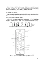
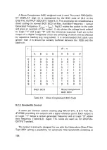
Page 105: ...vailable giving a digital coding of the indicated frequen cy 9 2 1 Digital Coded Frequency Output This is a 26 pin socket givi ng output voltage levels in a BCD code Each decade of the FREQUENCY DISPLAY is separately represented Fig 9 1 X 104 X 103 X 102 X 10 X 10 X 10 l ___ ____I 3__ ___I s____ _l 7_ __14 ____ 1 ____ oI 0 010 019 011 020 Rear Panel Digital Output Socket X 10 2TI IT Fig 9 1 Connec...

Page 106: ...ble runs greater than 2 m should be suitably buffered between the 1026 and the cable run r 9 r A B c D A B c D 0 0 0 0 0 1 0 0 1 1 1 0 0 0 0 0 0 1 2 0 1 0 0 1 1 1 0 3 1 1 0 0 0 1 1 0 4 0 0 1 0 1 0 1 0 5 1 0 1 0 0 0 1 0 6 0 1 1 0 1 1 0 0 7 1 1 1 0 0 1 0 0 8 0 0 0 1 1 0 0 0 9 1 0 0 1 0 0 0 0 8421 BCD Nines Complement 8421 BCD Table 9 1 Nines Complement BCD Code 9 2 2 Bandwidth Control A seven pin Ca...

Page 107: ...changed on a printed circuit in the 2021 before using this mode A further use requiring an external interface would be to activate the EVENT MARKER of a 2305 Level Recorder at each change over frequency This would allow the use of non calibrated paper while still retaining logarithmically spaced frequency marks Bandwidth Control Pin No s 1 0 0 0 0 0 0 Output 2 1 0 0 0 0 0 Code 3 1 1 0 0 0 0 in any...

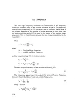
Page 108: ...od of the applied trigger waveform This is the difference between the two frequencies applied to the modulator Thus T 61 ff X 60 f where ft fixed oscillator frequency fv variable oscillator frequency and the output voltage E of the discriminator E E V0 X t 1 T 61 V0 X t1 ff X 60 f Thus the output frequency of the variable oscillator f is E 61 fv V ff X 60 1 0 X t1 The frequency appearing at the ou...

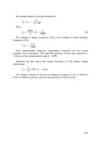
Page 109: ...ency stabilization networks for the crystal oscillator are unnecessary The specified stability of the fixed oscillator is 20 p p m for a temperature range 0 70 C Equation 3 also shows the output frequency to DC sweep voltage relationship f x 1o3 X E 1 kHz 0 3 The range of values of E for the full frequency sweep of 1 Hz to 10kHz is 0 75 V to 8 25 V giving a transfer characteristic of 0 75 mV Hz 10...

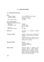
Page 110: ... Hz 3 V RMS Rayleigh 3 16 Hz 10Hz 31 6 Hz 100Hz 5 3 V RMS Dependent on Compressor Speeds Fig 4 8 Frequency counter with six digit Nixie read out Time base 0 5 sec Accuracy 0 1 Hz Analogue logarithmic frequency meter range 1 Hz to 10kHz 0 to 13 oct Accuracy 5 of reading Manual Automatic Linear Automatic Logarithmic External Electronic single or repetitive with indicator lamps for sweep direction Sh...

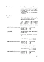
Page 111: ... to 2000kHz 100 to 1000 Hz m in 1 Hz to 10 kHz 1000 to 10 000 Hz min 1 Hz to 10kHz SWEEP RATE control accuracy Position 0 1 Position 1 2 Position 2 10 Not calibrated 2 o 1 Logarithmic SWEEP RATE control accuracy SWEEP RATE control accuracy Two sets of three ranges each covering a 20 dB x 10 Continuously adjustable by a calibrated 10 turn potentiometer 0 1 to 1 oct min 1 Hz to 2kHz 5Hz to 10kHz Pos...

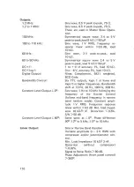
Page 112: ...11 V accuracy 1 load 10 kr 0 to 6 V accuracy 5 load 10 kr Nines Complement 8421 weighted BCD Code Six TTL outputs logic 1 at lower and logic 0 at higher frequencies Bandwidth shift at 10Hz 30Hz 100Hz 300Hz Sine wave 1 Hz to 10kHz following the frequency of the Exciter Control follows mid band frequency in narrow band random mode Constant ampli tude 1 V RMS Frequency response linear within 0 2 dB M...

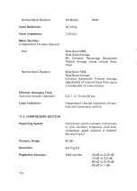
Page 113: ...dient Indicating Meter Calibration Sine 1 3 10 30 100 300 and 1000 g 1 Hz to 10 000 Hz 1 3 10 30 100 300 and 1000 in sec 0 01 0 03 in 10Hz to 2000Hz 0 1 0 3 in 3 16 Hz to 1000Hz 1 3 10 in 1 Hz to 200Hz 0 01 0 03 0 1 0 3 1 and 3 g JSeC 10Hz to 10 000 Hz Linear or 6 dB octave weighted 0 to 10 dB of range 0 2 dB of meter reading 10 to 20 dB of range 0 4 dB of meter reading 0 to 10 dB of range 0 4 dB ...

Page 114: ...e RMS 6 Constant Percentage Bandwidth filtered Average using internal Slave filter Wide Band RMS Wide Band Average Constant Bandwidth Filtered Average Bandwidth of internal Slave filter equal to bandwidth of noise chosen 0 3 1 3 10 and 30 sec Independent channel indication of over load and compressor control Compressor speed increases continuous ly with oscillator frequency until max compressor sp...

Page 115: ...nd RMS Wide Band Average 6 Constant Percentage Bandwidth filtered Average using internal Slave filter Wide Band RMS Wide Band Average Constant Bandwidth Filtered Average Bandwidth of internal slave filter equal to bandwidth of noise chosen Manual choice of either vibration meter Automatic choice of larger channel Thump free cross over External All relevant sections interlocked Safety limits refere...

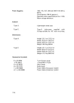
Page 116: ...ithin specifications for 10 Mains voltage deviation Lightweight metal case Type A instrument supplied with fittings suitable for 19 rack mounting Height 31 1 em 12 2 in Width 43 0 em 16 8 in Depth 50 0 em 19 7 in Weight 30 9 kg 68 lb Height 31 1 em 12 2 in Width 55 0 em 21 6 in Depth 50 0 em 19 7 in Weight 31 2 kg 68 5 lb 7 pin Cannon plugs 1 Amp 250 V Fuses Neon lamps Scale lamps Power Cable Euro...

Page 117: ......

Page 118: ......

Page 119: ......

Page 120: ...ucers Impedance Heads Accelerometer Preamplifiers Vibration Meters Accelerometer Calibrators Magnetic Transducers Capacitive Transducers Complex Modulus Apparatus VIBRATION TESTING Exciter Controls Sine Exciter Controls Sine Random Exciter Equalizers Random or Shock Exciters Power Amplifiers Programmer Units Stroboscopes STRAIN MEASUREMENTS Strain Gauge Apparatus Multi point Panels Automatic Selec...

Reviews: