© Brüel & Kjaer Vibro GmbH/4 mm ds821 / 21.7.15 /technical specifications subject to change / C104958.001 / V02
l
18
EN
4.1.2
Displacement sensor for rear-side mounting
The sensor for rear-side mounting is assembled with the help of a sensor holder which prefera-
bly includes an integrated bulkhead receptacle.
•
Fix the displacement sensor using a retainer that is appropriate for the type of installation.
We recommend using the holder AC-101.
4.2
Assembling the driver (oscillator/demodulator)
Assemble either:
•
with assembly adapter on a hat-rail
•
with assembly adapter via screw mounting on a firm surface
The oscillator must be mounted electrically insulated on its mounting socket and inside a pro-
tective housing, because the oscillator housing is part of the instrinsically safe circuit. The
distance of the oscillator housing to adjacent oscillators, or any other conductive part of the
housing, must always be above 2 mm. The mounting socket ensures that this minimum gap is
observed.
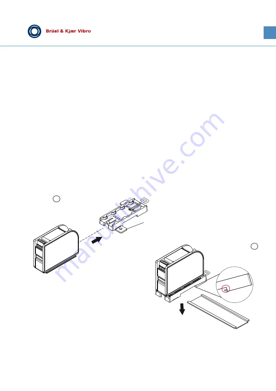
4.2.1 Mounting on hat-rail
*For mounting on a hat-rail, the mounting tabs for screw mounting can be separated at the predetermined breaking point.
1.
For screw mounting, break off both tabs and attach the driver with the assembly adapter by
sliding it into place
(figure
)
.
2.
Affix the assembly adapter to a hat-rail (DIN EN 60715 TH35):
Place rear part of the assembly adapter (see figure above, item A) onto the guides of the
1
*
2
A


