background image

Operating the VIBROCONTROL 1500  

VIBROCONTROL 1500 

VC1500EN / C103845.002 / V 09 / 14.04.2015 

- 45 - 

With 

L1BC, L2BC, L1temp 

and

 L2temp 

no relay response lag time


for the 

limit value violation is preselectable.  Signaling  of these events takes place 

immediately after violation of the set limit values. 


Fig. 41: Limit settings 

 
With further paging through the menu points using the buttons 

 and 

 the 

display with setting options for the measuring range and input filter frequency 

are reached. 


Fig. 42: Setting for the measuring range and highpass corner frequency 
 

Possible measuring range:


10; 20; 40; 50; 100; 200 

mm/s

 (0.5; 1,0; 2; 2.5; 5.0; 10.0 

in/s

 ) 

A plausibility check when changing the measurement range with respect to 

the pre-set limit values is  not performed. This means, for example, it is 

possible to set the measuring range smaller than the limit values. The correct 

configuration is the sole responsibility of the user. 
 

Possible high pass corner frequency:


1, 3, 10 Hz.  Please note that through  selection of the corner frequency all 

vibrations with frequencies lower than the selected corner frequency will be 

suppressed. 
 

Note: 

When a high pass  corner frequency is edited it is necessary to carry 

out a reset of the instrument.  This happens automatically when the 

selected changes to the settings are stored.  

Summary of Contents for VIBROCONTROL 1500

Page 1: ...VIBROCONTROL 1500 2 channel Monitoring Device for Bearing Vibrations Rolling element Bearing Condition and Temperature with Diagnostic Remote Monitoring Operating Instructions...

Page 2: ...ns electronic mechanical photocopying recording or otherwise without prior written permission from Br el Kj r Vibro GmbH The right to make changes at any time without notice is reserved Copyright 2015...

Page 3: ...gnal detection 8 2 3 General 9 2 4 Relay functions 9 3 Technical Data 11 4 Installation 16 4 1 With the installation of the VIBROCONTROL 1500 the following are to be observed 16 4 2 Mounting in an AC...

Page 4: ...1 Switching off the automatic reference value determination 35 7 7 2 General advice for bearing condition analysis 36 7 8 Trend display and prognosis 37 7 9 Rolling element bearing condition and tempe...

Page 5: ...for the system Reliability VIBROCONTROL 1500 is equipment which is reliable in service and corresponds to the state of the art technology Every instrument leaves our works in an error free and safe c...

Page 6: ...ion For the measurement and monitoring of temperatures of type PT 100 temperature sensors may also be applied in addition to the vibration sensors For operation of the instrument a power supply of 18...

Page 7: ...ng up is also possible using the VIBROCONTROL 1500 Control Center Software The connections for the power supply measurement sensors analogue and contact outputs as well as the CAN Bus interface are ma...

Page 8: ...ange signals of 4 20 mA per sensor proportional to the characteristic variable are available at the analogue outputs 2 2 3 Display value and bandwidth Acquisition of the measured data is done by vibra...

Page 9: ...ge is activated If the current measured value falls below the limit value during the response lag time the event message limit value violated is deactivated and upon a renewed limit value violation th...

Page 10: ...ing OK fault is by means of an LED the output of this signal is by means of a set of potential free switch over contacts With an error free operation the green LED at the instrument front panel lights...

Page 11: ...1Hz to 1kHz 3Hz to 1kHz 10 Hz to 1kHz adjustable in the menu Filter slope Acc to ISO 2373 60 dB decade with high pass 1 3 10 Hz 40 dB decade with low pass 1 kHz Limit values Adjustable with push butt...

Page 12: ...from the standard factor of 100 mV g Analogue output 4 20 mA for the RMS value of vibration velocity of channel A and channel B proportional to the set measuring range Max load at the analogue output...

Page 13: ...inutes DFT analysis of bearing condition Frequency range 500 5 000 Hz Sampling rate 15 000 Hz No of samples 800 No of lines 240 Nominal resolution 18 75 Hz Measurement and calculation time appr 5 seco...

Page 14: ...g vibration measurement at 80 Hz 2 1digit within the filter ranges 1 3 10 1 000 Hz 10 1digit at the corner frequencies 10 20 1digit Frequency response According to ISO 2373 60 dB dec transition steepn...

Page 15: ...211x with 1 x VIBROCONTROL 1500 0 C 45 C Operating temperature range in protective housing AC 211x with 2 x VIBROCONTROL 1500 0 C 40 C Humidity max 95 non condensing Sensors for vibration and rolling...

Page 16: ...of the connections there is a danger of plugging the connectors into the wrong socket with a wrong connection the instrument could be destroyed Dangerous voltages may be connected at the relay contac...

Page 17: ...L 1500 unit and the power supply AC 4111 is already established Remove the VIBROCONTROL 1500 unit from the DIN Rail before mounting or connecting other parts Disconnect all Phoenix plugs in the lower...

Page 18: ...OCONTROL 1500 unit in a protective housing AC 211x The trim levels of the protective housing AC 211x with mounted Vibrocontrol unit Fig 3 One VIBROCONTROL 1500 in protective housing Order code VIBROCO...

Page 19: ...00EN C103845 002 V 09 14 04 2015 19 Fig 5 Two VIBROCONTROL 1500 units in protective housing Order code VIBROCONTROL 1500 02 DC Fig 6 Two VIBROCONTROL 1500 units with power supply in protectiv housing...

Page 20: ...VIBROCONTROL 1500 Connections 20 VC1500EN C103845 002 V 09 14 04 2015 5 Connections Upper terminal strip Lower terminal strip Fig 7 VIBROCONTROL 1500 connection terminals 1st row 2nd row...

Page 21: ...d Channel B Sensor connections acceleration sensor CCS 8 SE Shield 9 GND 0 VA 10 SIG Positive signal input 11 SIG Negative signal input 12 POWER Sensor power 13 NC Not used 14 NC Not used DC current o...

Page 22: ...negative power 42 SE Shield PT100 B 43 SUP PT 100 positive power 44 IN PT 100 signal input 45 COM PT 100 negative power 46 SE Shield 5 3 Connection terminal layout lower terminal strip CAN Bus 23 CAN...

Page 23: ...to dangerous voltage and the plug is connected incorrectly the dangerous voltage could be connected on the ground connection Pin 26 of the reset input Take care of using the right connection for the...

Page 24: ...SIG and GND as well as between SIG and POWER must be made For testing the error free function of the sensor a test voltage is measured between SIG and SIG The permissible voltage range lies between 8...

Page 25: ...lamp Color of wire Signal 42 yellow black GN YE SE Schield 3 5 red RD SIG Sensor Signal 2 4 white WH COM 0 VA Sensor Signal Ground 39 orange OR PT 100 41 blue BU PT 100 40 black BK PT 100 green GN PT...

Page 26: ...sible For an estimation of the cable length the following formula can be used V voltage peak max U F m A S e capacitanc cable Specific C Hz Frequency f A n consumptio power amplifier Charge I A power...

Page 27: ...n to the menu and further initialization the instrument can be operated as a single channel instrument with only one sensor connected to channel A Note If only one sensor in connected e g in channel A...

Page 28: ...e VIBROCONTROL 1500 instrument by simultaneously pushing the and pushbuttons Fig 10 Display of the hardware and software version numbers The version numbers are only examples If subsequently an error...

Page 29: ...etting menu by pushing the MENU pushbutton to carry out changes to the settings that deviate from the standard settings made at the works This interrupts the initialization procedure This is indicated...

Page 30: ...of the measured value at channel A as well as both set limit values 7 4 Measuring the temperatures Note The VIBROCONTROL allows temperature measurement in the range 10 C 120 C By pushing the button a...

Page 31: ...ton is pushed while this is being displayed the current information about the limit value violation is deleted from the display Only the next arbitrary violation of a limit value leads to a new displa...

Page 32: ...As soon as a reference value is formed and indicated an additional third display with the designation BC Bearing condition appears in the display which is formed as follows This quotient is the bearin...

Page 33: ...OL 1500 Control Center Software the trend and frequency analysis of rolling element bearing condition can be displayed with a higher resolution and in a greater extent Course of the measurement of the...

Page 34: ...8 h the instantaneous RMS value of acceleration Im and the average value Avg are displayed In addition the bearing condition variable can now also be calculated and displayed Fig 21 Result of the bea...

Page 35: ...nce value If this behavior of the automatic Reference value re calculation is not desired it can be switched off by changing the parameter AutoRef to non auto But with this parameter setting the refer...

Page 36: ...line is formed The frequency of this one line is the evaluated average value of the three considered frequency lines As the weighting for the calculation of average values the respective RMS values of...

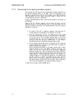
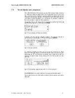
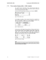
Page 37: ...is selected by pushing the buttons and and the selection is confirmed with ENTER Fig 23 Trend display with bearing vibrations A display with the channel selection appears The desired channel is selec...

Page 38: ...ted time period until the LIM 2 value is violated If no clear calculation is possible the following display appears Fig 27 Indeterminate prognosis a prediction is not possible Please note This predete...

Page 39: ...es an area for the trend from 30 x 8 hours and an area for the trend from 30 x 240 hours For reasons of a simplified recording the time axis is reversed on the left the oldest and on the right the mos...

Page 40: ...om the storage area 30 x 8 hours see fig 23 The contents of all storage areas can be selected in unchanged form only over the optionally available VIBROCONTROL 1500 Control Center Software Here the tr...

Page 41: ...ed appears The desired channel is selected with the help of the buttons and and the analysis is started with the button ENTER Fig 31 Channel selection During execution of the frequency analysis the fo...

Page 42: ...he measured data appears The desired channel is selected using the buttons and and confirmed with the button ENTER Fig 35 Channel selection In the upper line of the display the measured value of beari...

Page 43: ...machine running status for rolling element bearing condition and trend measurements are carried out in this menu Select the following display using the buttons and and confirm with the button ENTER Fi...

Page 44: ...y the value can be increased or decreased with the buttons and If the arrow keys are held down when modifying the limit values L1 v and L2 v the parameter is changed in increments of 0 1 mm s After 5...

Page 45: ...cy Possible measuring range 10 20 40 50 100 200 mm s 0 5 1 0 2 2 5 5 0 10 0 in s A plausibility check when changing the measurement range with respect to the pre set limit values is not performed This...

Page 46: ...takes place For this the current measured value of bearing vibration is considered The Machine On value is entered as a percentage of the selected measuring range As long as the actual measured value...

Page 47: ...e rolling element bearing condition reference value When a bearing is exchanged it is necessary to delete the data determined for the old bearing and to determine new data Therefore a reset of the BC...

Page 48: ...e entered one after the other with the help of the buttons and and each number is confirmed with the button ENTER after it is entered Fig 48 Password entry After entry of the correct password the disp...

Page 49: ...o measurement takes place at this channel Note As long as no sensor is connected to the sensor connection terminals and the sensitivity is not set to OFF the instrument will signal a fault Fig 49 Sett...

Page 50: ...s With the help of buttons and the value to be changed is selected and confirmed with ENTER Using the buttons and the values can be changed The new settings are confirmed with the button ENTER With th...

Page 51: ...tric mm s C to Imperial in s F Fig 53 Changing the units Setting the automatic reference value determination With the help of the buttons and can be switched between automatic AutoRef auto and manuel...

Page 52: ...eneral password 1500 is to be changed select Yes in the display and confirm by pushing ENTER Fig 56 Password change Now enter the master password 7327 and confirm with ENTER Fig 57 Enter the master pa...

Page 53: ...new password should be saved Using the buttons and select either NO or YES and confirm your selection by pushing ENTER If YES is confirmed the new password overwrites the default password 1500 supplie...

Page 54: ...ier of channel B 3 Not assigned 4 Not assigned 5 Not assigned 6 Not assigned 7 Internal error supply voltage of the analogue part out of range 8 Overheating of the instrument the temperature inside th...

Page 55: ...dog is not reset by the occurrence of an error the Watchdog counter overflows and an instrument RESET follows RAM test The RAM memory test takes place in an interrupt at 15kHz approx 66 s In each inte...

Page 56: ...vide power for one VIBROCONTROL 1500 instrument and it is intended for mounting on a DIN rail AC 4111 description Input data Input voltage 100 VAC 240 VAC Frequency 47 63 Hz Current consumption 300 mA...

Page 57: ...the unit and it is intended for mounting on a DIN rail AC 4601 description Input data Input voltage 100 VAC 240 VAC Frequency 45 65 Hz Current consumption Appr 0 86 A at 120 VAC nominal load appr 0 47...

Page 58: ...Accessories 58 VC1500EN C103845 002 V 09 14 04 2015 10 3 USB CAN interfaceconverter AC 4201 The converter serves the connection and regulation of up to 40 VIBROCONTROL 1500 units to a PC Fig 62 Examp...

Page 59: ...User dialogue Overview VIBROCONTROL 1500 VC1500EN C103845 002 V 09 14 04 2015 59 11 User dialogue Overview Fig 63 Structure of the menu controlled user dialogue...

Page 60: ...the VIBROCONTROL 1500 be calibrated every 5 years This will ensure that the correct functionality of the system is checked and that the certification according to the quality standard is maintained 1...

Page 61: ...and C Tick VIBROCONTROL 1500 VC1500EN C103845 002 V 09 14 04 2015 61 14 CE Decleration and C Tick We declare the conformity with the EMV requirement of the australian Government authority AMCA accorda...

Reviews: