background image

Chapter 2 — Operation

Output and Supply Connections


Preamplifiers Types 2663 and 2663 B

User Manual

Brüel & Kjær

12

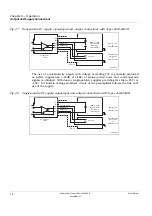
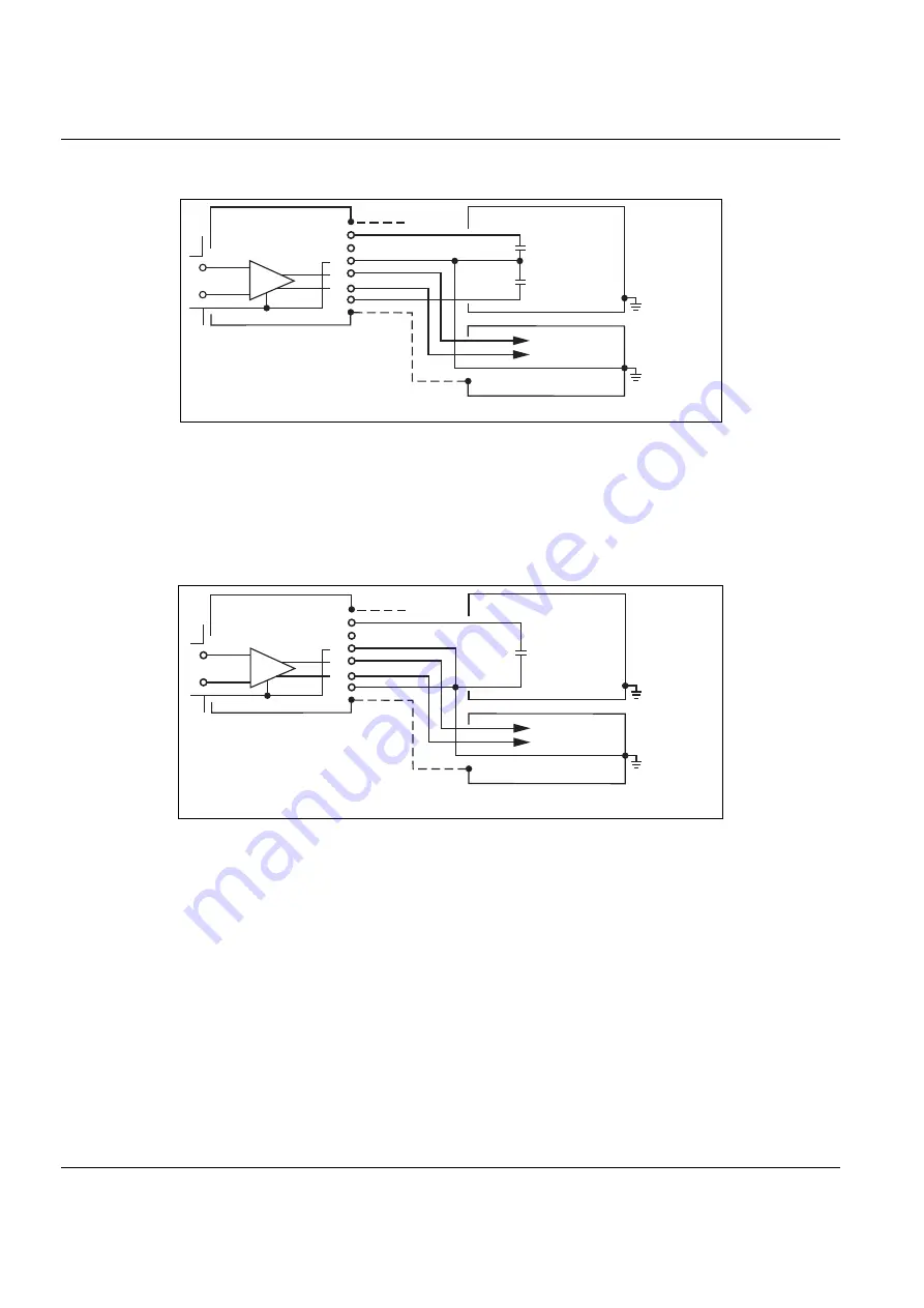
Fig.2.7

Dual-polarity DC supply, signal-input and -output connections with Types 2663/2663 B

The use of a dual-polarity supply with voltage exceeding 20 V is generally preferred
as better suppression (<60 dB at 1 kHz) of mains-carried noise and common-mode
signals is obtained. With dual or single-polarity supplies providing less than ±20 V (or
+20 V), the built-in voltage stabiliser circuit of the preamplifier follows the line volt-
age of the supply.

Fig.2.8

Single-polarity DC supply, signal-input and -output connections with Types 2663/2663 B

+

-

+

-

E
D
C
B
A
F

Signal Ground
AC Output
DC Output

Preamplifier

2663

Chassis

Readout

±20V to ±32V

Dual Polarity

DC Supply

(max. 30mA)

Chassis only

to

mains Ground

Signal Ground

plus chassis

to

mains Ground

891981/1

+

-

+

-

E
D
C
B

A
F

Signal Ground
AC Output
DC Output

Preamplifier

2663

Chassis

Readout

±20V to ±32V

Dual Polarity

DC Supply

(max. 30mA)

Chassis only

to

mains Ground

Signal Ground

plus chassis

to

mains Ground

891982/1

Summary of Contents for 2663

Page 1: ...00 Germany 49 421 17 87 0 Hong Kong 852 2548 7486 Hungary 36 1 215 83 05 Ireland 353 1 807 4083 Italy 39 0257 68061 Japan 81 3 5715 1612 Republic of Korea 82 2 3473 0605 Netherlands 31 318 55 9290 Norway 47 66 77 11 55 Poland 48 22 816 75 56 Portugal 351 21 4169 040 Singapore 65 377 4512 Slovak Republic 421 25 443 0701 Spain 34 91 659 0820 Sweden 46 33 225 622 Switzerland 41 44 8807 035 Taiwan 886...

Page 2: ...BE 1068 12 Preamplifiers Types 2663 and 2663 B User Manual ...

Page 3: ......

Page 4: ...Revision April 2003 BE 1068 12 Brüel Kjær Preamplifiers Types 2663 and 2663 B User Manual Preamplifiers Types 2663 and 2663 B ...

Page 5: ...ive environments It should not be operated in the presence of flammable liquids or gases Warnings Switch off all power to equipment before connecting or disconnecting their digital inter face Failure to do so could damage the equipment Whenever it is likely that the correct function or operating safety of the apparatus has been impaired it must be made inoperative and be secured against unintended...

Page 6: ... and F 11 2 5 Circuit Adjustment for Acceleration Measurement 12 Low frequency Cut off Adjustment 14 High frequency Cut off Adjustment 14 Output Bias Adjustment 15 Sensitivity Gain Adjustment 15 Grounded Floating 16 2 6 Circuit Adjustment for Velocity Measurement 16 Changing the Low pass Filter 18 Changing the High pass Filter 19 Velocity Sensitivity 20 3 Operating Characteristics 21 3 1 Lower Lim...

Page 7: ...r 32 4 2 Measuring and Recording Instrumentation 33 5 Specifications 35 5 1 Specifications 36 6 Service and Repair 37 6 1 Service 38 6 2 Repair 38 A Appendix Ground Loop Noise 39 A 1 Ground Loop Phenomena 40 Index 41 ...

Page 8: ...Preamplifiers Types 2663 and 2663 B User Manual BE 1068 12 1 Chapter 1 Introduction ...

Page 9: ... this manual before operat ing the preamplifier to ensure proper usage and measurement 1 2 Preamplifiers Types 2663 and 2663 B Fig 1 1 Preamplifier Type 2663 1 2 1 Uses and Features The following applies to both Type 2663 and Type 2663 B Uses Vibration measurement on aircraft Measurement of vibration in severe environments Vibration monitoring on industrial machinery General vibration measurement ...

Page 10: ...r is constructed from milled aluminium The removable side cover is fitted with a rubber seal which pro tects the electronics from dirt oil humidity and other environmental contamination The preamplifier can be powered from either a single ended or dual polarity supply The input connector is a 2 pin TNC socket The output connector is a 6 pin bayonet socket containing both AC and DC signal output pi...

Page 11: ...ad justable to give a cut off frequency from 0 5 Hz to 1 kHz For frequencies greater than 3 Hz the sensitivity is adjustable between l mV pC and 100 mV pC All the adjustments discussed above are made by replacing the appropriate resistors with ones of the desired value and resoldering Standard metal film resistors are used and to provide ease of access these resistors and the grounded Floating con...

Page 12: ...Preamplifiers Types 2663 and 2663 B User Manual BE 1068 12 5 Chapter 2 Operation ...

Page 13: ...have an advantage in that they can be mounted close to accelerometers thus eliminating the need for long input cables which are prone to mechanically induced triboelectric noise The preamplifiers have a 4 mm 0 15 in diameter hole at each corner of their hous ing for mounting purposes They also contain an M 3 Metric Insert for grounding Fig 2 1 Mounting of Preamplifier Types 2663 and 2663 B Ensure ...

Page 14: ... where a high level of electromagnetic radiation exists as radiation pickup can introduce noise In such a case the connection of a differential acceler ometer as described in section 2 3 2 is preferred Plugs and Cables Connection of a single ended accelerometer to the preamplifiers should be made us ing one of the single screened low noise accelerometer cables specified in section 4 1 These are fi...

Page 15: ...ype 2663 2663 B using the Microplug TNC socket Adaptor Type JJ 0207 with single screened low noise accelerometer cable Fig 2 3 A section of Type 2663 2663 B s circuit board is shown with the side cover removed The Floating Remove Jumper allows you to choose between a grounded or floating connection For a Single ended Floating configuration remove the connection jumper between the two pins on the s...

Page 16: ...d two core low noise accelerometer cable Single screened Cable Connections With single screened cable the two inner conductors are used to connect both poles of the accelerometer output to the preamplifier input as shown in Fig 2 4 To prevent the formation of a ground loop the cable screen should be connected to the outer shield of the accelerometer output only or the preamplifier input only but n...

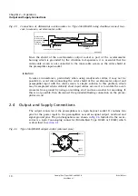
Page 17: ...imple solution to this problem which may be employed when relatively short input cables are used is to isolate the accel erometer from ground by using an isolating stud and mica washer for mounting If this is not possible then disconnect the grounded floating connection on the pream plifier circuit 2 4 Output and Supply Connections The output connector of the preamplifiers is a 6 pin bayonet socke...

Page 18: ... different stages of the preamplifier circuit and is pulled high on overload This could for example be used to drive the event marker of a level recorder and can be used in systems for remotely recording or monitoring vibration signals 2 4 3 Signal Ground Connection Pin C The signal ground signal is output via pin C Since the 0 V line of the supply is part of the measurement system signal ground l...

Page 19: ...ing less than 20 V or 20 V the built in voltage stabiliser circuit of the preamplifier follows the line volt age of the supply Fig 2 8 Single polarity DC supply signal input and output connections with Types 2663 2663 B E D C B A F Signal Ground AC Output DC Output Preamplifier 2663 Chassis Readout 20V to 32V Dual Polarity DC Supply max 30mA Chassis only to mains Ground Signal Ground plus chassis ...

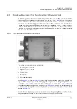
Page 20: ...s required for particular parameter values are printed on the shield Standard metal film resistors should be used Fig 2 9 Type 2663 2663 B with side cover removed The following parameters are adjustable Low frequency cut off High frequency cut off Output Bias Sensitivity Floating Grounded Both section 2 5 1 and section 2 5 2 deal with the procedures needed to change the high and low frequency cut ...

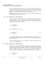
Page 21: ...t off frequency from 0 5 Hz to 1 kHz The formula for the high pass frequency as printed on the circuit shield is as follows In this application 2 5 1 To change the low frequency cut off exchange resistors and with resistors of the value calculated by formula 2 5 1 The response of the lower limiting frequency is shown in section 3 1 Note The minimum low frequency cut off increases for high sensitiv...

Page 22: ...tput bias is preadjusted to 2 5 V and is also adjustable by replacing RB with a resistor of the appropriate value For a dual polarity supply this can be adjusted from 0 0 to 5 5 V referred to supply ground For a single polarity supply the choice is between 0 5 and 5 5 V The following formula is used to calculate RB Thus the value for RB can be found 2 5 3 To change the output bias exchange resisto...

Page 23: ...he sensitivity exchange resistor RG with a resistor of the value calculated from formula 2 5 4 2 5 5 Grounded Floating Fig 2 10 Grounded Floating connection shown with left Floating and right Grounded input config uration This has already been discussed in section 2 3 1 and is used when choosing between single ended grounded and single ended floating input connections RG 1 69 10 5 Gain 10 3 ...

Page 24: ... the preamplifier to integrate the signal Fig 2 11 Preset frequency response Types 2663 2663 B Fig 2 11 shows the preset frequency response of the preamplifiers which is obtained from combining the responses of the low and high pass filter pair The low pass filter determines the high frequency cut off FLP of the preamplifier and is preset to 33 kHz A filter roll off rate of 40 dB dec is necessary ...

Page 25: ...ole low pass filter is needed to achieve the necessary roll off rate of 20 dB for integration Note It is not recommended to integrate complex signals such as single shocks and impulses See section 2 6 1 section 2 6 2 and section 2 6 3 on dealing with the steps necessary to change the preamplifiers to an integrator 2 6 1 Changing the Low pass Filter The low pass filter must be changed from a two po...

Page 26: ...ation begins is 10 Hz since this will suppress any low frequency noise caused by transducer temperature varia tions Fig 2 13 Resistor connections when using the preamplifiers as an integrator 2 6 2 Changing the High pass Filter The two resistors which determine the characteristics of the high pass filter are and The value of resistor is determined by the damping coefficient and the cut off frequen...

Page 27: ...Calculation of the gain acceleration sensitivity is covered in section 2 5 4 Shown in Fig 2 14 are both the measured and calculated responses of the preamplifi ers when used as an integrator In this example the measured frequency response of the preamplifiers compares well with the ideal curve However component toleranc es may cause some deviation from the calculated frequency response of the inte...

Page 28: ... 12 21 Fig 2 14 Measured and ideal frequency response curves for preamplifier operating as an integrator The measured curve compares very well to the ideal response 10 Hz 100 Hz 1 kHz 0 dB 10 dB 20 dB 30 dB 40 dB 20 Hz 50 Hz 200 Hz 500 Hz 1 Hz 2 Hz 5 Hz 892067 1e Ideal Measured FLP FHP 10 Hz k 0 37 Type 2663 Integration ...

Page 29: ...Chapter 2 Operation Circuit Adjustment for Velocity Measurement Preamplifiers Types 2663 and 2663 B User Manual Brüel Kjær 22 ...

Page 30: ...Preamplifiers Types 2663 and 2663 B User Manual BE 1068 12 23 Chapter 3 Operating Characteristics ...

Page 31: ...amplifier has an low input resistance 10 M then the frequency response of the preamplifier will be affected The response curve will rise at a frequency just below the lower limiting frequency 3 dB cutoff Normal ly the input impedance of a piezoelectric transducer exceeds 10 M so this is not a problem However in cases where it may occur the user can change the cut off frequency of the high pass fil...

Page 32: ...iers for different input and output load capacitance is shown in Fig 3 3 and Fig 3 4 These graphs can be used to determine which lengths of input and output cable can be used with the preamplifier without their shunt capacitance influencing the frequency range of interest for the measurement Fig 3 3 Upper limiting frequency response of Type 2663 for different input loads 1 Hz 10 Hz 1 dB 0 dB 1 dB ...

Page 33: ...usted to 33 kHz 3 dB The cut off frequency may be adjusted between 250 Hz and 33 kHz and with reduced specifications to 200 kHz The formula for calcu lating the cut off frequency is given in section 2 5 2 Shown in Fig 3 5 is the frequency response of the low pass filter using different resistor values Fig 3 6 shows the upper limiting frequency of the preamplifiers for different gain settings when ...

Page 34: ...ers of different charge sensitivity this may be readjusted as discussed in section 2 5 4 for an output sensitivity between 1 and 100 mV pC For sensitivities greater than 25 mV pC the minimum lower limiting frequency increases Fig 3 7 shows the minimum lower limiting frequency for given gain settings Fig 3 7 Minimum lower limiting frequency versus gain setting 1 kHz 10 kHz 0 dB 2 dB 4 dB 6 dB 8 dB ...

Page 35: ...h input capacitance of the preamplifiers makes the influence of input cable shunt ca pacitance on the sensitivity of the system insignificant 3 4 Phase Response The typical phase response of the the preamplifiers for the preset frequency range 0 5 Hz to 33 kHz is shown in Fig 3 8 Note that changing the upper or lower limiting frequency will alter the phase characteristics accordingly Fig 3 8 Phase...

Page 36: ...ivity set to 1 mV pC and a 2 nF capacitor terminating the input simulating the source capacitance of a transducer with connection cable Fig 3 9 Third octave noise spectrum produced by Types 2663 when powered from a 28 V dual polarity supply The measurement was made using a Brüel Kjaer Dual Channel Real time Frequency Analyzer Type 2133 With higher values of input source capacitance the output nois...

Page 37: ...User Manual Brüel Kjær 30 Fig 3 10 Broadband 3 Hz to 20 kHz noise as a function of input source capacitance 200 pC Noise Refered to Input 100 pC 50 pC 20 pC 10 pC 1 2 5 10 20 50 Input Source Capacitance nF 1 2 5 10 20 50 100 200 500 Accelerometer Cable 90 pF m length m 893290 1e 10 3 pC 1 mV pC 100 mV pC ...

Page 38: ...Preamplifiers Types 2663 and 2663 B User Manual BE 1068 12 31 Chapter 4 Accessories ...

Page 39: ...12 may be connected to the TNC input of the preamplifiers using the supplied Adaptor Type JJ 0207 Type JJ 0207 is shown in Fig 4 1 and con nects the accelerometer housing via the cable screens to the positive pole of the preamplifier input and housing thus completing the measurement system signal ground line Fig 4 1 Front view of Adaptor Type JJ 0207 Brüel Kjær Cable Type Part Identities Material ...

Page 40: ...d can be obtained with plugs already fitted Table 4 2 Screened two core cable for connection of differential transducers When ordering cables the appropriate plug or plugs must be specified Suitable two pole plugs are Type JP 0209 for 180o C 356o F operation as shown in Fig 4 3 below Fig 4 4 shows the plug of Type AO 0250 which has a cable already fitted Brüel Kjær Cable Type Material Max Temp Len...

Page 41: ... F 3 m Type AO 0250 G 5 m Type AO 0250 H 10 m Type AO 0250 I 15 m 4 1 3 Output Connector The preamplifiers are supplied with a 6 pin Plug Type JJ 0615 shown in Fig 4 5 and for convenience the output connector is shown with pin designations in figure 4 6 Fig 4 5 6 pin Plug Type JJ 0615 output connector with solder connections supplied with Types 2663 Type 2663 B is supplied with Crimp Connector Typ...

Page 42: ...ith pin designations 4 2 Measuring and Recording Instrumentation Brüel Kjær supply a wide range of piezoelectric transducers which are measuring and recording instrumentation that may be used with Types 2663 and 2663 B For detailed information on equipment specifications consult Brüel Kjær directly or go to www bksv com 890751e V V Overload DC out AC out Signal Ground A F E B C D ...

Page 43: ...Preamplifiers Types 2663 and 2663 B User Manual Brüel Kjær 36 ...

Page 44: ...Preamplifiers Types 2663 and 2663 B User Manual BE 1068 12 37 Chapter 5 Specifications ...

Page 45: ... A 10 6 P F 42 Ex SPL MIL specified Input Connector 2 pole TNC socket Case Earth Connection Metric Insert M3 POWER Supply Voltage Single Supply 20 V to 32 V or Dual Supply 20 V to 32 V Supply Current 30 mA Isolation Signal ground isolated from chassis GAIN Charge conversion factor 3 Hz Adjustable between 1 100 mV pC 3 Hz Adjustable between 1 25 mV pC Preadjusted to 1 mV pC OUTPUT MAX OUTPUT SIGNAL...

Page 46: ...Preamplifiers Types 2663 and 2663 B User Manual BE 1068 12 39 Chapter 6 Service and Repair ...

Page 47: ...eir specification and operate satisfactorily for many years If a fault does occur which affects the operation or the safety of the preamplifiers then dis connect the power supply to prevent the risk of further damage 6 2 Repair For repair contact your local Brüel Kjaer service representative Under no circumstances should repair be attempted by persons not qualified in the service of electronic ins...

Page 48: ...Preamplifiers Types 2663 and 2663 B User Manual BE 1068 12 41 Appendix A Ground Loop Noise ...

Page 49: ...closed and the transducer is grounded to the structure then Vg perhaps a few volts will cause a current to flow through the accelerometer cable and through the amplifier circuits introducing an error volt age that adds to the signal To avoid the formation of ground loops it is essential that the signal ground line is grounded at only one point in the measurement system preferably at the readout or...

Page 50: ...Preamplifiers Type 2663 and 2663 B User Manual BE 1068 12 43 Index ...

Page 51: ...0 Extension Connector Type JJ 0032 30 F factory preset 25 floating grounded connection 12 Floating Remove Jumper 8 formula for calculating cut off frequency 24 formula for high pass frequency 14 formula for low pass frequency 14 Frequency response 25 G general vibration work 7 ground loop 7 9 11 Ground Loop Phenomena 40 ground potential difference 40 Grounded Floating 16 grounded floating connecti...

Page 52: ... response 17 R radiation pickup 11 ready made cables 10 Recording Instrumentation 33 Repair 38 resistance 18 response characteristics 18 S Sensitivity 25 Sensitivity Gain Adjustment 15 Service 38 sharp attenuation 17 shock levels 6 shunt capacitance 23 24 26 Signal Ground Connection 11 Single ended Connections 7 single ended floating 3 Single ended Floating configuration 8 single ended grounded 3 ...

Page 53: ......

Page 54: ...00 Germany 49 421 17 87 0 Hong Kong 852 2548 7486 Hungary 36 1 215 83 05 Ireland 353 1 807 4083 Italy 39 0257 68061 Japan 81 3 5715 1612 Republic of Korea 82 2 3473 0605 Netherlands 31 318 55 9290 Norway 47 66 77 11 55 Poland 48 22 816 75 56 Portugal 351 21 4169 040 Singapore 65 377 4512 Slovak Republic 421 25 443 0701 Spain 34 91 659 0820 Sweden 46 33 225 622 Switzerland 41 44 8807 035 Taiwan 886...

Reviews: