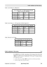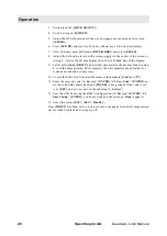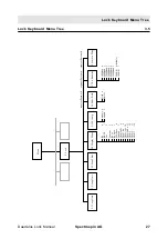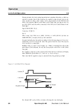
Operation
22
Spectrospin AG
Daedalus Lock Manual
Cont. ex.
7: Regulator Output 8 x expanded (total screen: 30.5Hz
@ 2D for standard bore magnet)
DIAGLoLi
8: only for diagnosticDIAG-sin9: only for diagnostic
DIAG-cos10: only for diagnisticDIAGCoEx11:
only
for diagnosticDIAG 112: reseved for further options
DIAG 2
13: reseved for further options
DIAG 3
14: reseved for further options
2.5 Z0-Comp.
disable
0: The Z0 compensation input is separated from the H0
current source.
enable
1: The Z0 compensation input is switched to the cur-
rent source if the Z0 piggy board (Z4P2934) is placed
on the LCB.
2.6 SHIFT/FIELD
Field
0: during Autolock the field will be adjusted
Shift
1: during Autolock the lock frequency will be adjusted
(password required) this mode is automatic enabled
during a ‘lock’ task executed from UXNMR.
2.7 RS-Baudrate
300Baud
0 Baud rate for the Lock-Display (password required)
600Baud
1
1200Baud
2
2400Baud
3
4800Baud
4
9600Baud
5
19.2KB
6 (default baud rate)
38.4KB
7
2.8 Lockin PStep
0.0..20.0dB
The transmitter power is reduced by this amount after a
lock-in (password required).
Manual Lock-In
3.2
The first step in manually locking on a solvent when the correct field value is not
known is to search for the lock signal. One approach to finding the lock signal is to
set the sweep amplitude to the maximum (100), increase the lock power (e.g., to 0
dBm), and increase the lock gain (e.g., to 120 dB). The lock DC should be set to ap-
proximately –75 and the sweep rate to 0.2 Hz. Adjust the field value until the lock
signal is approximately centered on the screen, and then begin to reduce the sweep
amplitude. If the signal disappears from the screen during this process, it may be
brought back by re-adjusting the field value. Eventually, the lock signal should be
centered on the screen with the sweep amplitude reduced to a value in the range of 2
to 5. The lock power and gain should also be reduced to a level suitable to the par-
ticular solvent. Finally, the lock phase must be adjusted. The phase is optimized
when the amplitude of the sweep wiggles is the same for both directions of the field
sweep. If the wiggles in one direction are larger than those in the other, adjust the
lock phase to correct the imbalance. Having the correct phase is important to
achieving lock-in.
Caution: Sidebands
It may be difficult, especially if the lock signal is very narrow, to observe the lock
signal when the sweep amplitude is fully open, despite the high power and gain set-
Summary of Contents for DAEDALUS
Page 1: ...BRUKER BRUKER SPECTROSPIN AG SERVICE MANUAL DAEDALUS LOCK Version BSMS 004 ...
Page 6: ...Contents 6 Spectrospin AG Daedalus Lock Manual ...
Page 14: ...8 Spectrospin AG Daedalus Lock Manual ...
Page 16: ...10 Spectrospin AG Daedalus Lock Manual ...
Page 26: ...General Description 20 Spectrospin AG Daedalus Lock Manual ...
Page 36: ...Operation 30 Spectrospin AG Daedalus Lock Manual ...
Page 56: ...Lock Transmitter 50 Spectrospin AG Daedalus Lock Manual ...
Page 64: ...Lock Receiver 58 Spectrospin AG Daedalus Lock Manual ...
Page 68: ...19F RX Option 62 Spectrospin AG Daedalus Lock Manual ...
Page 85: ...Installation Daedalus Lock Manual Spectrospin AG 79 Installation 11 2 ...
Page 86: ...Z0 Compensation Option 80 Spectrospin AG Daedalus Lock Manual ...
Page 90: ...Technical Data 84 Spectrospin AG Daedalus Lock Manual ...
Page 92: ...Trouble Shooting 86 Spectrospin AG Daedalus Lock Manual ...
Page 98: ...BSMS service tool 92 Spectrospin AG Daedalus Lock Manual ...
Page 107: ...Error Descriptions Daedalus Lock Manual Spectrospin AG 101 ...
Page 108: ...Lock Error Messages 102 Spectrospin AG Daedalus Lock Manual ...
Page 114: ...Appendix 108 Spectrospin AG Daedalus Lock Manual ...
Page 122: ...116 Spectrospin AG Daedalus Lock Manual ...
Page 123: ...Daedalus Lock Manual Spectrospin AG 117 Lock Transmitter Index B ...
Page 124: ...118 Spectrospin AG Daedalus Lock Manual ...
Page 125: ...Daedalus Lock Manual Spectrospin AG 119 Lock Transmitter Index C ...
Page 126: ...120 Spectrospin AG Daedalus Lock Manual ...
Page 127: ...Daedalus Lock Manual Spectrospin AG 121 19F Transmitter Option Index A ...
Page 128: ...122 Spectrospin AG Daedalus Lock Manual ...
Page 129: ...Daedalus Lock Manual Spectrospin AG 123 Lock Receiver Index C ...
Page 130: ...124 Spectrospin AG Daedalus Lock Manual ...
Page 131: ...Daedalus Lock Manual Spectrospin AG 125 Lock Receiver Index D E ...
Page 132: ...126 Spectrospin AG Daedalus Lock Manual ...
Page 133: ...Daedalus Lock Manual Spectrospin AG 127 19F Receiver Option Index A ...
Page 134: ...128 Spectrospin AG Daedalus Lock Manual ...
Page 135: ...Daedalus Lock Manual Spectrospin AG 129 Lock Controller Index A ...
Page 136: ...130 Spectrospin AG Daedalus Lock Manual ...
Page 137: ...Daedalus Lock Manual Spectrospin AG 131 Lock Controller Index B C ...
Page 138: ...132 Spectrospin AG Daedalus Lock Manual ...
Page 139: ...Daedalus Lock Manual Spectrospin AG 133 Lock RS232 Biggy Board ...
Page 140: ...134 Spectrospin AG Daedalus Lock Manual ...
Page 141: ...Daedalus Lock Manual Spectrospin AG 135 Z0 Compensation Option ...
Page 142: ...136 Spectrospin AG Daedalus Lock Manual ...
Page 143: ...Daedalus Lock Manual Spectrospin AG 137 Cables ...
Page 144: ...138 Spectrospin AG Daedalus Lock Manual ...
Page 145: ...Daedalus Lock Manual Spectrospin AG 139 Test Equipment Index A ...


