Lock Transmitter
42
Spectrospin AG
Daedalus Lock Manual
Digital-Analog Converter (DAC)
5.1.9
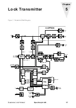
The transmitter level controlling signal is produced in a DAC (IC5). This DAC is
controlled by the Serial Bus and IC3 (OP) converts the current output of the DAC
into a proportional voltage. The transmitter power range is adjusted via the Potenti-
ometers POT2 and POT3. Thereafter the transmitter maximum power is first set
with POT2 and then the minimum power with POT3. Both of the temperature sen-
sors IC31 and IC32 are compensating the transmitter gain temperature drift. IC31
corrects the gain elevation angle drift and IC32 the gain offset drift.
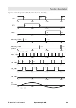
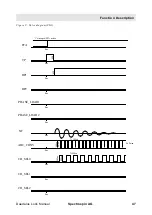
A second DAC (IC1) may be used for switching and is quickly set via a 7 Bit Bus
(EPROM_BUS). Because the In and Out Flanking of the transmitter pulse is con-
trolled by this DAC the transmitter pulses are able to be generated in different
shapes. The different shape forms are stored in the EPROM.
An OP (IC3) adds both of the DAC signals and delivers the control signal UAGC.
This is possible because the control voltage UAGC acts in a linear fashion upon the
transmitter power. The Zener Diode limits the UAGC to a maximum of 12 V.
PFP / FFA-Mode Switching
5.1.10
The transmitter signal from the AGC amplifier is divided after the amplifier MOD1.
One part is used for the X-Option (e.g. 19F); the other part is amplified again in
MOD2. In normal lock operation (PFP Mode) the transmitter signal is switched us-
ing IC4 and sent via L19 to the transmitter output (J3). Therefore C79, L19 and
C119 act as a quarter wave. The print version ECL01 has an additional attenuator
between the switch IC4 and L19 to reduce the transmitter signal. Thus the output
level at J4 is 10dB less then the level of version ECL00. The recitfied transmitter
signal may be used for diagnostics via the DIAG_1 connection.
In FFA mode IC4 switches the signal to the FFA amplifier (T7). IC4 is controlled by
a TTL signal via the FFA connection. A logic high level switches on the FFA ampli-
fier supply voltage.
If there is a lock substance other than Deuterium used the control connection
L_SUBST is logic high. This switches the two Deuterium transmitter signals off.
Summary of Contents for DAEDALUS
Page 1: ...BRUKER BRUKER SPECTROSPIN AG SERVICE MANUAL DAEDALUS LOCK Version BSMS 004 ...
Page 6: ...Contents 6 Spectrospin AG Daedalus Lock Manual ...
Page 14: ...8 Spectrospin AG Daedalus Lock Manual ...
Page 16: ...10 Spectrospin AG Daedalus Lock Manual ...
Page 26: ...General Description 20 Spectrospin AG Daedalus Lock Manual ...
Page 36: ...Operation 30 Spectrospin AG Daedalus Lock Manual ...
Page 56: ...Lock Transmitter 50 Spectrospin AG Daedalus Lock Manual ...
Page 64: ...Lock Receiver 58 Spectrospin AG Daedalus Lock Manual ...
Page 68: ...19F RX Option 62 Spectrospin AG Daedalus Lock Manual ...
Page 85: ...Installation Daedalus Lock Manual Spectrospin AG 79 Installation 11 2 ...
Page 86: ...Z0 Compensation Option 80 Spectrospin AG Daedalus Lock Manual ...
Page 90: ...Technical Data 84 Spectrospin AG Daedalus Lock Manual ...
Page 92: ...Trouble Shooting 86 Spectrospin AG Daedalus Lock Manual ...
Page 98: ...BSMS service tool 92 Spectrospin AG Daedalus Lock Manual ...
Page 107: ...Error Descriptions Daedalus Lock Manual Spectrospin AG 101 ...
Page 108: ...Lock Error Messages 102 Spectrospin AG Daedalus Lock Manual ...
Page 114: ...Appendix 108 Spectrospin AG Daedalus Lock Manual ...
Page 122: ...116 Spectrospin AG Daedalus Lock Manual ...
Page 123: ...Daedalus Lock Manual Spectrospin AG 117 Lock Transmitter Index B ...
Page 124: ...118 Spectrospin AG Daedalus Lock Manual ...
Page 125: ...Daedalus Lock Manual Spectrospin AG 119 Lock Transmitter Index C ...
Page 126: ...120 Spectrospin AG Daedalus Lock Manual ...
Page 127: ...Daedalus Lock Manual Spectrospin AG 121 19F Transmitter Option Index A ...
Page 128: ...122 Spectrospin AG Daedalus Lock Manual ...
Page 129: ...Daedalus Lock Manual Spectrospin AG 123 Lock Receiver Index C ...
Page 130: ...124 Spectrospin AG Daedalus Lock Manual ...
Page 131: ...Daedalus Lock Manual Spectrospin AG 125 Lock Receiver Index D E ...
Page 132: ...126 Spectrospin AG Daedalus Lock Manual ...
Page 133: ...Daedalus Lock Manual Spectrospin AG 127 19F Receiver Option Index A ...
Page 134: ...128 Spectrospin AG Daedalus Lock Manual ...
Page 135: ...Daedalus Lock Manual Spectrospin AG 129 Lock Controller Index A ...
Page 136: ...130 Spectrospin AG Daedalus Lock Manual ...
Page 137: ...Daedalus Lock Manual Spectrospin AG 131 Lock Controller Index B C ...
Page 138: ...132 Spectrospin AG Daedalus Lock Manual ...
Page 139: ...Daedalus Lock Manual Spectrospin AG 133 Lock RS232 Biggy Board ...
Page 140: ...134 Spectrospin AG Daedalus Lock Manual ...
Page 141: ...Daedalus Lock Manual Spectrospin AG 135 Z0 Compensation Option ...
Page 142: ...136 Spectrospin AG Daedalus Lock Manual ...
Page 143: ...Daedalus Lock Manual Spectrospin AG 137 Cables ...
Page 144: ...138 Spectrospin AG Daedalus Lock Manual ...
Page 145: ...Daedalus Lock Manual Spectrospin AG 139 Test Equipment Index A ...

