Operation
24
Spectrospin AG
Daedalus Lock Manual
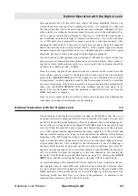
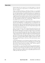
During shimming, these lock parameters are not terribly important. It is important,
however, to set the lock power approximately 6 to 10 dB under saturation and to op-
timize the lock phase.
During critical NMR experiments (e.g., difference experiments), it is very important
to have good shim values and optimal lock parameters to ensure good field stability.
The most important indicator of an optimal lock parameter set is a high signal-to-
noise ratio of the lock signal. To achieve this, first the lock power should be set as
high as possible and yet not so high as to cause saturation. Increase the lock power
in small steps and observe the lock line on the screen. The lock level should increase
steadily in response to the increase in power level; when it no longer increases, or
even begins to decrease, saturation has been reached. Depending on the lock sol-
vent, this may happen rather quickly (e.g., at approximately –30 dBm for Acetone).
The optimum lock power level is a few dB below saturation.
It is also important to choose the best lock receiver gain (lock gain). In general, if
the lock DC is set appropriately (i.e., at approximately –75) it is sufficient to set the
lock gain so that the lock line is in the upper part of the screen. The goal here is to
best use the ranges of the A/D converter and the signal processor. This occurs when
the lock gain is set as high as possible without causing receiver gain overflow, which
can be recognized by the presence of a very noisy lock signal, and a decrease in lock
level with a further increase in lock gain.
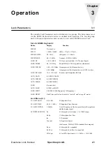
Finally, the regulator should be optimized using loop gain and loop time (see Lock
Parameters on page 21 ). A large (i.e., less negative) loop gain value enables a better
field disturbance compensation, which is what is desired. However, if the signal-to-
noise ratio of the lock signal is not sufficient, too high a loop gain causes the H0
field to be noise modulated. When this occurs, the lock line oscillates visibly on the
screen. Of course, this noise modulation then shows up in the NMR spectrum, which
is highly undesirable. Thus, a useful rule of thumb is that the better the signal-to-
noise ratio of the lock signal is, the higher the loop gain may be set. A typical loop
gain setting is –35 dB. For optimum regulator performance, though, the loop gain
cannot be set independently of the loop time. A typical loop time value is 0.05 s
and, in general, longer loop times are necessary for lock signals with poorer signal-
to-noise ratios.
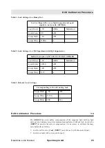
Lock settings appropriate for various conditions are listed below in Table 1, Table 2,
and Table 3. The settings shown in Table 1 are appropriate for a lock signal with
quite a high signal-to-noise ratio, those in Table 2 are appropriate for a lock signal
with a fairly poor signal-to-noise ratio, and those in Table 3 cause the regulator to
behave the same as that of the old analog lock system.
One final comment is in order. If two different lock solvents yield lock signals hav-
ing the same screen line position (lock level) but with a different lock gain and pow-
er setting used for each, then the system signal-to-noise ratio varies inversely with
respect to the lock gain. For example, if one solvent requires 10 dB more gain than
the other to achieve the same signal level, the corresponding signal-to-noise ratio is
l0 dB less than that for the other solvent.
Summary of Contents for DAEDALUS
Page 1: ...BRUKER BRUKER SPECTROSPIN AG SERVICE MANUAL DAEDALUS LOCK Version BSMS 004 ...
Page 6: ...Contents 6 Spectrospin AG Daedalus Lock Manual ...
Page 14: ...8 Spectrospin AG Daedalus Lock Manual ...
Page 16: ...10 Spectrospin AG Daedalus Lock Manual ...
Page 26: ...General Description 20 Spectrospin AG Daedalus Lock Manual ...
Page 36: ...Operation 30 Spectrospin AG Daedalus Lock Manual ...
Page 56: ...Lock Transmitter 50 Spectrospin AG Daedalus Lock Manual ...
Page 64: ...Lock Receiver 58 Spectrospin AG Daedalus Lock Manual ...
Page 68: ...19F RX Option 62 Spectrospin AG Daedalus Lock Manual ...
Page 85: ...Installation Daedalus Lock Manual Spectrospin AG 79 Installation 11 2 ...
Page 86: ...Z0 Compensation Option 80 Spectrospin AG Daedalus Lock Manual ...
Page 90: ...Technical Data 84 Spectrospin AG Daedalus Lock Manual ...
Page 92: ...Trouble Shooting 86 Spectrospin AG Daedalus Lock Manual ...
Page 98: ...BSMS service tool 92 Spectrospin AG Daedalus Lock Manual ...
Page 107: ...Error Descriptions Daedalus Lock Manual Spectrospin AG 101 ...
Page 108: ...Lock Error Messages 102 Spectrospin AG Daedalus Lock Manual ...
Page 114: ...Appendix 108 Spectrospin AG Daedalus Lock Manual ...
Page 122: ...116 Spectrospin AG Daedalus Lock Manual ...
Page 123: ...Daedalus Lock Manual Spectrospin AG 117 Lock Transmitter Index B ...
Page 124: ...118 Spectrospin AG Daedalus Lock Manual ...
Page 125: ...Daedalus Lock Manual Spectrospin AG 119 Lock Transmitter Index C ...
Page 126: ...120 Spectrospin AG Daedalus Lock Manual ...
Page 127: ...Daedalus Lock Manual Spectrospin AG 121 19F Transmitter Option Index A ...
Page 128: ...122 Spectrospin AG Daedalus Lock Manual ...
Page 129: ...Daedalus Lock Manual Spectrospin AG 123 Lock Receiver Index C ...
Page 130: ...124 Spectrospin AG Daedalus Lock Manual ...
Page 131: ...Daedalus Lock Manual Spectrospin AG 125 Lock Receiver Index D E ...
Page 132: ...126 Spectrospin AG Daedalus Lock Manual ...
Page 133: ...Daedalus Lock Manual Spectrospin AG 127 19F Receiver Option Index A ...
Page 134: ...128 Spectrospin AG Daedalus Lock Manual ...
Page 135: ...Daedalus Lock Manual Spectrospin AG 129 Lock Controller Index A ...
Page 136: ...130 Spectrospin AG Daedalus Lock Manual ...
Page 137: ...Daedalus Lock Manual Spectrospin AG 131 Lock Controller Index B C ...
Page 138: ...132 Spectrospin AG Daedalus Lock Manual ...
Page 139: ...Daedalus Lock Manual Spectrospin AG 133 Lock RS232 Biggy Board ...
Page 140: ...134 Spectrospin AG Daedalus Lock Manual ...
Page 141: ...Daedalus Lock Manual Spectrospin AG 135 Z0 Compensation Option ...
Page 142: ...136 Spectrospin AG Daedalus Lock Manual ...
Page 143: ...Daedalus Lock Manual Spectrospin AG 137 Cables ...
Page 144: ...138 Spectrospin AG Daedalus Lock Manual ...
Page 145: ...Daedalus Lock Manual Spectrospin AG 139 Test Equipment Index A ...


