Function Description
Daedalus Lock Manual
Spectrospin AG
43
FFA Amplifier
5.1.11
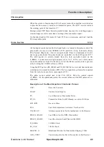
When the system is functioning in FFA (Fourier) mode this amplifier is switched on
to provide the necessary increase in transmitter power. The R127 resistor controls
the working point of the transistor T7.
During normal PFP Mode the anti-parallel diodes improve the switching suppres-
sion and suppress at the same time a loading of the transmitter signal.
On the other hand in FFA mode L19 and C119 are on resonance and don’t load the
FFA transmitter pulse.
Pulse-Section
5.1.12
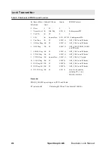
All the digital control pulses for the digital lock are created in the pulse section. The
pulse banks are saved in two EPROM’s (IC28 and IC29). Every lock mode (Reset,
FFA, Normal, Diagnostic...) has its own pulse bank. There is a maximum of two kil-
obytes per pulse bank. The pulse banks are controlled via the shift register IC27.
The shift register is serially loaded from the lock controller board via the
P_BNK0...3 connections and optocouplers (IC16, IC17, IC18). An 11 Bit counter
counts the addresses from 0 to 2K (A0 to A10). The 1MHz counter clock is generat-
ed by dividing the 10 MHz reference (IC30).
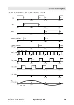
Using the RCP pulses (RX_BLNK and TX_BLNK) the receiver and transmitter are
switched out in normal lock mode (PFP). The two signals are galvanically separated
from the lock electronics by an optocoupler (IC15).
The pulse section central unit is the PAL (IC14). Here the control signals
(P_BNK0...10), the pulsebank pulses, the counter values and the RCP pulses are co-
ordinated.
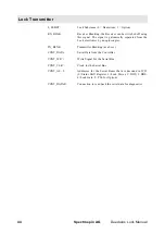
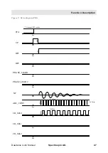
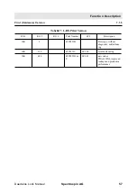
Description of the Most Important Controller Pulses:
CLR
~
:
Reset the Counters
LOAD
~
:
Counter Load Impulse
TP:
Lock Electronics Transmitter Pulse
TP_F0:
Transmitter Pulse for HP-Preamp, can drive 50 Ohms
RP1, RP2:
Receiver Pulse
FFA:
Fast Field Adjustment, activates ‘Fast Lock In’
CH_SEL0..2:
Address connections for the multiplexer in the Receiver
PHASE_LOAD1:
Load Phase 0 in the DDS (Transmitter)
PHASE_LOAD2:
Load the selected Lock Phase in the lDDS
D_10MHz
10 MHz Clock
PL_CLK:
1 MHz Clock
SHAPE0...6:
Blackman Window for Transmitter-Shaping (7 Bit)
ADC_CONV:
Conversion pulse for the A/D converter in the Receiver
Summary of Contents for DAEDALUS
Page 1: ...BRUKER BRUKER SPECTROSPIN AG SERVICE MANUAL DAEDALUS LOCK Version BSMS 004 ...
Page 6: ...Contents 6 Spectrospin AG Daedalus Lock Manual ...
Page 14: ...8 Spectrospin AG Daedalus Lock Manual ...
Page 16: ...10 Spectrospin AG Daedalus Lock Manual ...
Page 26: ...General Description 20 Spectrospin AG Daedalus Lock Manual ...
Page 36: ...Operation 30 Spectrospin AG Daedalus Lock Manual ...
Page 56: ...Lock Transmitter 50 Spectrospin AG Daedalus Lock Manual ...
Page 64: ...Lock Receiver 58 Spectrospin AG Daedalus Lock Manual ...
Page 68: ...19F RX Option 62 Spectrospin AG Daedalus Lock Manual ...
Page 85: ...Installation Daedalus Lock Manual Spectrospin AG 79 Installation 11 2 ...
Page 86: ...Z0 Compensation Option 80 Spectrospin AG Daedalus Lock Manual ...
Page 90: ...Technical Data 84 Spectrospin AG Daedalus Lock Manual ...
Page 92: ...Trouble Shooting 86 Spectrospin AG Daedalus Lock Manual ...
Page 98: ...BSMS service tool 92 Spectrospin AG Daedalus Lock Manual ...
Page 107: ...Error Descriptions Daedalus Lock Manual Spectrospin AG 101 ...
Page 108: ...Lock Error Messages 102 Spectrospin AG Daedalus Lock Manual ...
Page 114: ...Appendix 108 Spectrospin AG Daedalus Lock Manual ...
Page 122: ...116 Spectrospin AG Daedalus Lock Manual ...
Page 123: ...Daedalus Lock Manual Spectrospin AG 117 Lock Transmitter Index B ...
Page 124: ...118 Spectrospin AG Daedalus Lock Manual ...
Page 125: ...Daedalus Lock Manual Spectrospin AG 119 Lock Transmitter Index C ...
Page 126: ...120 Spectrospin AG Daedalus Lock Manual ...
Page 127: ...Daedalus Lock Manual Spectrospin AG 121 19F Transmitter Option Index A ...
Page 128: ...122 Spectrospin AG Daedalus Lock Manual ...
Page 129: ...Daedalus Lock Manual Spectrospin AG 123 Lock Receiver Index C ...
Page 130: ...124 Spectrospin AG Daedalus Lock Manual ...
Page 131: ...Daedalus Lock Manual Spectrospin AG 125 Lock Receiver Index D E ...
Page 132: ...126 Spectrospin AG Daedalus Lock Manual ...
Page 133: ...Daedalus Lock Manual Spectrospin AG 127 19F Receiver Option Index A ...
Page 134: ...128 Spectrospin AG Daedalus Lock Manual ...
Page 135: ...Daedalus Lock Manual Spectrospin AG 129 Lock Controller Index A ...
Page 136: ...130 Spectrospin AG Daedalus Lock Manual ...
Page 137: ...Daedalus Lock Manual Spectrospin AG 131 Lock Controller Index B C ...
Page 138: ...132 Spectrospin AG Daedalus Lock Manual ...
Page 139: ...Daedalus Lock Manual Spectrospin AG 133 Lock RS232 Biggy Board ...
Page 140: ...134 Spectrospin AG Daedalus Lock Manual ...
Page 141: ...Daedalus Lock Manual Spectrospin AG 135 Z0 Compensation Option ...
Page 142: ...136 Spectrospin AG Daedalus Lock Manual ...
Page 143: ...Daedalus Lock Manual Spectrospin AG 137 Cables ...
Page 144: ...138 Spectrospin AG Daedalus Lock Manual ...
Page 145: ...Daedalus Lock Manual Spectrospin AG 139 Test Equipment Index A ...

