Lock Receiver
56
Spectrospin AG
Daedalus Lock Manual
Low Frequency Section (LF Section)
7.1.3
LF-Amp with variable Gain
This unit, with a gain range of 30 dB, produces a low frequency signal with constant
amplitude. This guarantees maximum input range and the best possible resolution
from the D/A converter which follows.
A SL-6140 AGC from Plessy is once again used for its advantages with noise figure,
phase drift and gain range.
Active Bandpassfilter
To eliminate possible disturbance frequencies and improve the S/N ratio, the low
frequency signal is actively filtered before digitization. A choice is made between
two filters - a bandpass filter with fo = 3.33 kHz with Q = 10 for normal operation or
a lowpass fliter with fo = 0.9 kHz for FFA operation.
The noise content of the normal filter is dominated by voltage noise of the OP’s at a
voltage gain of 40. Therefore we use a LT-1028 from Linear Technology as it is the
lowest noise OP on the market.
The noise requirements when using the FFA filter are less pronounced therefore we
use here a TL-072 from Texas Instruments.
Acquisition
7.1.4
An A/D converter digitizes the absorption and dispersion lock signals alternately
and send these serially via the Optocoupler (galvanic isolation) to the Lock Control-
ler Board for further processing.
A DSP101 from Burr Brown is used as A/D converter. This is a single channel SAR
converter (ENOB=14Bit). The SAR converter has the advantage that it is very exact
around zero. Since we regulate to zero this is exactly the converter we need. The
DSP101 contains in addition an ASIC; this prepares the necessary digital signals in
such a way that we need only three connnections (Clock, Serial Data, Frame Sync.)
on the signal processor. The AT76C120 from ATMEL is second source. In that case
another Logic and a pulse section would be required for the signal processor.
The Multiplexer HI3-0508A5 alternately switches the three low frequency channels
(Dispersions signal, Absorbtions signal, ext. Sensor) to the A/D converter. The sam-
pling rate is 40 kHz. This results in 13.333 kHz per channel which is four times the
IF frequency of the receiver.
The digital signals are sent via the 74HC541 driver, the HCPL 2631 optocoupler and
the 74HC14 Schmitt-Trigger to the signal processor. The clock is 1 MHz. All com-
ponents are placed on the receiver board.
Summary of Contents for DAEDALUS
Page 1: ...BRUKER BRUKER SPECTROSPIN AG SERVICE MANUAL DAEDALUS LOCK Version BSMS 004 ...
Page 6: ...Contents 6 Spectrospin AG Daedalus Lock Manual ...
Page 14: ...8 Spectrospin AG Daedalus Lock Manual ...
Page 16: ...10 Spectrospin AG Daedalus Lock Manual ...
Page 26: ...General Description 20 Spectrospin AG Daedalus Lock Manual ...
Page 36: ...Operation 30 Spectrospin AG Daedalus Lock Manual ...
Page 56: ...Lock Transmitter 50 Spectrospin AG Daedalus Lock Manual ...
Page 64: ...Lock Receiver 58 Spectrospin AG Daedalus Lock Manual ...
Page 68: ...19F RX Option 62 Spectrospin AG Daedalus Lock Manual ...
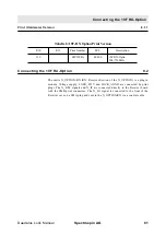
Page 85: ...Installation Daedalus Lock Manual Spectrospin AG 79 Installation 11 2 ...
Page 86: ...Z0 Compensation Option 80 Spectrospin AG Daedalus Lock Manual ...
Page 90: ...Technical Data 84 Spectrospin AG Daedalus Lock Manual ...
Page 92: ...Trouble Shooting 86 Spectrospin AG Daedalus Lock Manual ...
Page 98: ...BSMS service tool 92 Spectrospin AG Daedalus Lock Manual ...
Page 107: ...Error Descriptions Daedalus Lock Manual Spectrospin AG 101 ...
Page 108: ...Lock Error Messages 102 Spectrospin AG Daedalus Lock Manual ...
Page 114: ...Appendix 108 Spectrospin AG Daedalus Lock Manual ...
Page 122: ...116 Spectrospin AG Daedalus Lock Manual ...
Page 123: ...Daedalus Lock Manual Spectrospin AG 117 Lock Transmitter Index B ...
Page 124: ...118 Spectrospin AG Daedalus Lock Manual ...
Page 125: ...Daedalus Lock Manual Spectrospin AG 119 Lock Transmitter Index C ...
Page 126: ...120 Spectrospin AG Daedalus Lock Manual ...
Page 127: ...Daedalus Lock Manual Spectrospin AG 121 19F Transmitter Option Index A ...
Page 128: ...122 Spectrospin AG Daedalus Lock Manual ...
Page 129: ...Daedalus Lock Manual Spectrospin AG 123 Lock Receiver Index C ...
Page 130: ...124 Spectrospin AG Daedalus Lock Manual ...
Page 131: ...Daedalus Lock Manual Spectrospin AG 125 Lock Receiver Index D E ...
Page 132: ...126 Spectrospin AG Daedalus Lock Manual ...
Page 133: ...Daedalus Lock Manual Spectrospin AG 127 19F Receiver Option Index A ...
Page 134: ...128 Spectrospin AG Daedalus Lock Manual ...
Page 135: ...Daedalus Lock Manual Spectrospin AG 129 Lock Controller Index A ...
Page 136: ...130 Spectrospin AG Daedalus Lock Manual ...
Page 137: ...Daedalus Lock Manual Spectrospin AG 131 Lock Controller Index B C ...
Page 138: ...132 Spectrospin AG Daedalus Lock Manual ...
Page 139: ...Daedalus Lock Manual Spectrospin AG 133 Lock RS232 Biggy Board ...
Page 140: ...134 Spectrospin AG Daedalus Lock Manual ...
Page 141: ...Daedalus Lock Manual Spectrospin AG 135 Z0 Compensation Option ...
Page 142: ...136 Spectrospin AG Daedalus Lock Manual ...
Page 143: ...Daedalus Lock Manual Spectrospin AG 137 Cables ...
Page 144: ...138 Spectrospin AG Daedalus Lock Manual ...
Page 145: ...Daedalus Lock Manual Spectrospin AG 139 Test Equipment Index A ...

