112
HYPERION User Manual
Bruker Optik GmbH
Options and Accessories 5
5.1.2
Additional information about the GIR objective
Due to the exactly defined plane of incidence, the orientation of polarized light is main-
tained. For this reason, the GIR objective is ideal for measurements with polarized light.
☞
For information about polarizers, see section 5.4.
The GIR objective is especially well-suited for spectroscopic measurements of very thin
layers (e.g. impurities, monolayer structure) on highly reflecting substrates (e.g. metals).
Also for the determination of molecular orientations, the use of an IR polarizer is recom-
mended. However, for analyzing thin layers on paper or impurities in polymers, the GIR
objective is not suited.
When you analyze a very thin layer (< 100 nm) on a metallic surface using p-polarized
light (i.e. the IR light is polarized in parallel to the incidence direction), absorptions are
well-recognizable in the spectrum. If, however, s-polarized light (i.e. the IR light is polar-
ized perpendicular to the incidence direction) is used, the spectrum shows only very
weak or no absorption bands at all.
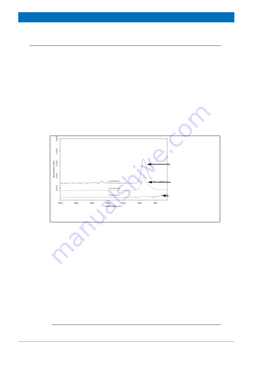
You can check the orientation of the polarized light by acquiring a sample spectrum of
the aluminum mirror
1
. When this sample spectrum has been acquired with p-polarized
light, there is a prominent absorption band at approx. 950 cm
-1
which results from the
aluminum oxide layer on the mirror surface. In case of s-polarized light, however, this
absorption band does not exist. See fig. 5.1.
As is usual practice for analyzing small sample areas, enclose the intended measure-
ment area using the knife-edge aperture. In case of the GIR objective, pay attention to
the following fact: Due to the grazing incidence angle of the IR beam, the measurement
spot is stretched approx. fourfold in the incidence direction of the IR beam, whereas per-
pendicular to the incidence direction of the IR beam, the diameter of the measurement
spot remains unchanged. To take this into account, set the knife-edge aperture to
25 µm x 100 µm to cover an area of 100 µm x 100 µm at the spectroscopic measure-
ment, for example. Note: Background measurement and sample measurement have to
be performed with identical knife-edge aperture setting.
Figure 5.1:
Sample spectra of a aluminum mirror acquired with the GIR objective using
differently polarized IR light
Spectrum acquired with
p-polarized IR light
Spectrum acquired with
s-polarized IR light
Spectrum acquired with
unpolarized IR light
1. The aluminum mirror is included in the standard delivery scope. Note: For measuring the background spec-
trum use the gold mirror which is included in the standard delivery scope as well.
Summary of Contents for HYPERION
Page 1: ...HYPERION User Manual I 24319 ...
Page 56: ...54 HYPERION User Manual Bruker Optik GmbH Overview 3 ...
Page 148: ...146 HYPERION User Manual Bruker Optik GmbH Repair and Maintenance 6 ...
Page 168: ...166 HYPERION User Manual Bruker Optik GmbH Specifications A ...
Page 172: ...170 HYPERION User Manual Bruker Optik GmbH Measurement parameters B ...
Page 174: ...172 HYPERION User Manual Bruker Optik GmbH Spare parts and consumables C ...
Page 175: ...173 Bruker Optik GmbH HYPERION User Manual D System diagram ...
Page 176: ...174 HYPERION User Manual Bruker Optik GmbH System diagram D ...


