138
HYPERION User Manual
Bruker Optik GmbH
Repair and Maintenance 6
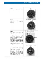
Step 2
Take the three pins out of the recesses
using the tweezers.
Step 3
Loosen the three slotted-head screws
at the inner ring using a small flat tip
screwdriver.
Remove the screws and the washers.
Step 4
Using the hex wrench, rotate the two
adjusting screws in such a way that
the inner ring is moved towards the
two springs. Rotate the two adjusting
screws until the distance between the
inner and the outer ring is as small as
possible at this place. This facilitates
removing the springs.
Take the two springs and the pins out
of the recesses using the tweezers.
Caution:
The springs may jump out of
the recess. Therefore, shield the bot-
tom side of the objective with your
hand.
Step 5
Remove the crystal assembly and
insert the replacement crystal assem-
bly.
When inserting the replacement crys-
tal assembly, pay attention to the ori-
entation of the inner ring.
Make sure that the two recesses of the
inner ring (i.e. recesses for inserting
the springs) are aligned with the corre-
sponding recesses of the outer ring.
Pins
Slotted-head screws plus washers
at the inner ring
Screws for adjusting the
crystal assembly in hori-
zontal direction
Springs
Recesses for inserting the springs
Summary of Contents for HYPERION
Page 1: ...HYPERION User Manual I 24319 ...
Page 56: ...54 HYPERION User Manual Bruker Optik GmbH Overview 3 ...
Page 148: ...146 HYPERION User Manual Bruker Optik GmbH Repair and Maintenance 6 ...
Page 168: ...166 HYPERION User Manual Bruker Optik GmbH Specifications A ...
Page 172: ...170 HYPERION User Manual Bruker Optik GmbH Measurement parameters B ...
Page 174: ...172 HYPERION User Manual Bruker Optik GmbH Spare parts and consumables C ...
Page 175: ...173 Bruker Optik GmbH HYPERION User Manual D System diagram ...
Page 176: ...174 HYPERION User Manual Bruker Optik GmbH System diagram D ...


