145
Bruker Optik GmbH
HYPERION User Manual
Repair and Maintenance 6
3.
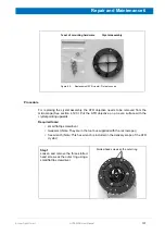
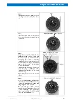
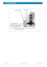
Insert the long part of the hex wrench straight into the opening. (See fig. 6.10a and
6.10b.) Note: The hex wrench has to snap in the head of the hex countersunk
screw.
4.
Actuate the rocker switch and pull the outer casing of the ATR objective downwards
until it snaps into place at pressure level 1. (See section 4.12.5.)
5.
Swing the ATR objective in the beam path.
6.
Put the plastic ring
1
on the microscope stage. Position the ring concentrically under-
neath the ATR objective.
7.
Move the microscope stage slowly upwards until the plastic ring pushes the ATR
crystal in the focus position. Note: The focus position is indicated acoustically by a
beep and optically by the In-focus LED (fig. 6.9a). When the ATR crystal has
reached the focus position, the In-focus LED turns from red to green for a short
moment. Then it goes off.
8.
While watching the signal display in OPUS (fig. 6.9b), correct the height setting of
the ATR crystal by slightly rotating the adjusting screw using the hex wrench. Cor-
rect the setting until the maximum signal intensity (amplitude value) is displayed in
OPUS.
Figure 6.10: a) ATR objective top side b) Inserting the hex wrench
Hex screw (countersunk) for adjusting
the height of the ATR crystal
1. The plastic ring is included in the delivery scope of the ATR objective.
Summary of Contents for HYPERION
Page 1: ...HYPERION User Manual I 24319 ...
Page 56: ...54 HYPERION User Manual Bruker Optik GmbH Overview 3 ...
Page 148: ...146 HYPERION User Manual Bruker Optik GmbH Repair and Maintenance 6 ...
Page 168: ...166 HYPERION User Manual Bruker Optik GmbH Specifications A ...
Page 172: ...170 HYPERION User Manual Bruker Optik GmbH Measurement parameters B ...
Page 174: ...172 HYPERION User Manual Bruker Optik GmbH Spare parts and consumables C ...
Page 175: ...173 Bruker Optik GmbH HYPERION User Manual D System diagram ...
Page 176: ...174 HYPERION User Manual Bruker Optik GmbH System diagram D ...


