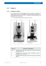
51
Bruker Optik GmbH
HYPERION User Manual
Overview 3
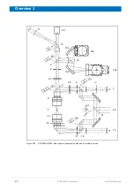
Component and Description
1
Visible light source (reflectance mode).
2
Iris aperture for setting the Koehler illumination: to adjust the visible light intensity and
the contrast in the reflectance mode. The lever for adjusting the iris diameter is situ-
ated on the right side of the microscope (E in fig. 3.10).
3
Three-position motorized mirror
Position 1: Only visible light can pass.
Position 2: Only IR light can pass.
Position 3: Both visible light and IR light can pass. A beam splitter (Option A689-R) is
required.
4
Aperture (optional): to define the measurement area in reflectance mode.
5
Four-position motorized mirror
Position 1: Transmittance mode (open).
Position 2: Reflectance mode (glass beamsplitter), for visible light.
Position 3) Reflectance mode for IR light (spectroscopic measurement) and VIS/IR
(viewing and spectroscopic measurement). 50% of the light is reflected by a mirror.
Position 4: Dichroic mirror that transmits only fluorescent light for fluorescence option
6
Objective
7
Sample
8
Aperture (manual or motorized knife-edge aperture): to define the sample area for the
analysis (transmittance or reflectance mode).
9
Three-position motorized mirror
Position 1: Viewing only (An opening allows visible light to reach the binocular eye-
piece or the camera port.)
Position 2: Spectral data acquisition only (IR beam is routed only to the detector using
a mirror.)
Position 3: Simultaneous viewing and spectral data acquisition (optional). (The IR
beam is directed to the detector, while the visible light is routed to the binocular eye-
piece or the camera port.)
10
Two-position, manually operated mirror
Position 1: All light goes to the binocular eyepiece (11).
Position 2: All light goes to the camera port (22).
11
Binocular eyepiece: to view the sample.
12
Two-position detector selection mirror:
Position 1: IR beam is routed to the standard detector 1 (14a)
Position 2: IR beam is routed to optional detector 2 (14b).
13a
Mirror: routes IR beam to detector 1 (14a).
13b
Mirror: routes IR beam to detector 2 (14b).
14a
Infrared detector
14b
IR detector or FPA detector (optional)
Summary of Contents for HYPERION
Page 1: ...HYPERION User Manual I 24319 ...
Page 56: ...54 HYPERION User Manual Bruker Optik GmbH Overview 3 ...
Page 148: ...146 HYPERION User Manual Bruker Optik GmbH Repair and Maintenance 6 ...
Page 168: ...166 HYPERION User Manual Bruker Optik GmbH Specifications A ...
Page 172: ...170 HYPERION User Manual Bruker Optik GmbH Measurement parameters B ...
Page 174: ...172 HYPERION User Manual Bruker Optik GmbH Spare parts and consumables C ...
Page 175: ...173 Bruker Optik GmbH HYPERION User Manual D System diagram ...
Page 176: ...174 HYPERION User Manual Bruker Optik GmbH System diagram D ...

