89
Bruker Optik GmbH
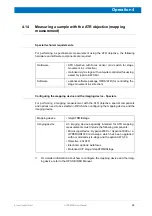
HYPERION User Manual
Operation 4
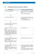
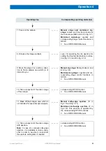
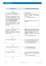
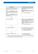
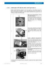
4.12.5
Setting contact pressure levels
The measurement technique ATR requires an intimate contact between ATR crystal and
sample to obtain meaningful sample spectra. In case of the ATR objective, the optimal
contact pressure is obtained by pressing the ATR crystal against the sample with a pres-
sure that is adequate to the degree of hardness of the sample. Five different pressure
levels can be set: pressure level 1 (contact pressure: 0.5 N) for very soft samples up to
pressure level 5 (contact pressure: 8 N) for very hard samples.
4.12.6
Focussing
In viewing mode
Proceed as follows:
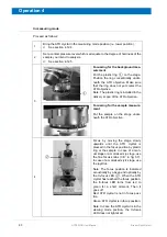
1.
Bring the ATR crystal in the viewing mode position (i.e. upper position). See
section 4.12.4.
2.
Focus on the sample by moving the stage slowly upwards.
➣
Attention:
When moving the stage upwards, take care the ATR crystal tip does not
hit the stage.
Potential risk of damaging the ATR crystal!
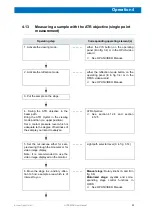
Setting a contact pressure level:
Actuate the rocker switch
①
and pull
the outer casing
②
of the ATR objec-
tive down until it snaps into place at the
desired pressure level.
Note: The currently set contact pres-
sure level is indicated by the red point
of the pressure level display
④
.
Then, release the rocker switch again.
Attention:
When setting a contact
pressure level, take care that the ATR
crystal tip
③
does not hit the stage.
Potential risk of damaging the ATR
crystal!
①
②
③
④
Summary of Contents for HYPERION
Page 1: ...HYPERION User Manual I 24319 ...
Page 56: ...54 HYPERION User Manual Bruker Optik GmbH Overview 3 ...
Page 148: ...146 HYPERION User Manual Bruker Optik GmbH Repair and Maintenance 6 ...
Page 168: ...166 HYPERION User Manual Bruker Optik GmbH Specifications A ...
Page 172: ...170 HYPERION User Manual Bruker Optik GmbH Measurement parameters B ...
Page 174: ...172 HYPERION User Manual Bruker Optik GmbH Spare parts and consumables C ...
Page 175: ...173 Bruker Optik GmbH HYPERION User Manual D System diagram ...
Page 176: ...174 HYPERION User Manual Bruker Optik GmbH System diagram D ...


