99
Bruker Optik GmbH
HYPERION User Manual
Operation 4
Solving possible problems
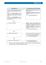
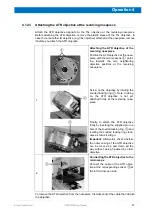
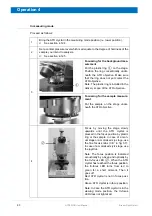
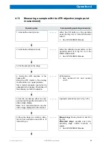
In case there is a problem, check whether:
• the distance between ATR crystal tip (with the ATR crystal being in the lower
measuring mode position) and sample surface is not more than 2 mm when
starting the ATR mapping measurement,
• the ATR objective cable is connected properly to the microscope,
• the motorized stage has been reset with an imaging device being selected in
OPUS,
• the correct stage option (
lstepATRMICstage
) has been selected in OPUS in the
mapping device setup and in the imaging device setup and
• the correct objective option (20x ATR) has been selected in OPUS in the map-
ping device setup and in the imaging device setup.
4.15
GIR objective - Important operating notes
4.15.1
General information
For defining the measurement area and for measurements with polarized light, it is of
crucial importance that the GIR objective
1
is attached at the revolving nosepiece with an
exact alignment.
☞
For information about measurements with polarized light in conjunction with the GIR
objective, see section 5.1.2.
The GIR objective is attached in an exactly aligned manner if the two VIS-GIR knobs
(see fig. 4.4) lie on an imaginary line which runs straight from the front to the back side of
the microscope. (Note: Only with this alignment of the GIR objective, it is ensured that
the incident light beam runs exactly from the right to the left.)
When you screw the GIR objective in the thread of the revolving nosepiece, however,
the exact alignment of the GIR objective is not always ensured a priori because the
threads vary slightly from microscope to microscope and from GIR objective to GIR
objective. For this reason, you first have to attach the GIR objective to the revolving
nosepiece and check the alignment of the GIR objective before starting the very first
measurement. (See section 4.15.5.) In case the GIR objective is not aligned as
described above, you have to readjust the alignment of the plane mirrors. (See
section 4.15.6.)
In case you have already readjusted the GIR objective but then you have removed it
from the revolving nosepiece, it is highly recommended to recheck the alignment before
using the GIR objective again. (See section 4.15.5.) When you screw the GIR objective
in the same thread of the revolving nosepiece again, normally a readjustment might not
be necessary.
1. GIR objective - Grazing Incidence Reflection Angle Objective
Summary of Contents for HYPERION
Page 1: ...HYPERION User Manual I 24319 ...
Page 56: ...54 HYPERION User Manual Bruker Optik GmbH Overview 3 ...
Page 148: ...146 HYPERION User Manual Bruker Optik GmbH Repair and Maintenance 6 ...
Page 168: ...166 HYPERION User Manual Bruker Optik GmbH Specifications A ...
Page 172: ...170 HYPERION User Manual Bruker Optik GmbH Measurement parameters B ...
Page 174: ...172 HYPERION User Manual Bruker Optik GmbH Spare parts and consumables C ...
Page 175: ...173 Bruker Optik GmbH HYPERION User Manual D System diagram ...
Page 176: ...174 HYPERION User Manual Bruker Optik GmbH System diagram D ...

