103
Bruker Optik GmbH
HYPERION User Manual
Operation 4
4.15.5
Checking the alignment of the GIR objective
➣
Important note:
Realigning
the GIR objective requires knowledge about the mirror
optics design and the functional principal of the GIR objective as well as about the
images generated in the VIS mode and in the GIR mode. For this reason, read thor-
oughly the sections 4.15.2 to 4.15.4 before starting to check the alignment of the
GIR objective and starting to realign the GIR objective, if required.
1.
Attach the GIR objective to the revolving nosepiece opposite to the standard 15x
objective. (Note: Due to lack of space, first remove the plastic purge shroud of the
standard 15x objective, if present.)
2.
Swing the GIR objective in the beam path. Make sure that the incident light beam
runs from the right (GIR) to the left (VIS).
3.
Set the mirror optics of the GIR objective to the viewing mode (VIS).
4.
Microscope: Activate the reflection mode.
5.
Microscope: Activate the viewing mode.
6.
Put the mirror on the microscope sample stage. (Note: The mirror is included in the
delivery scope.)
7.
Focus on the mirror by moving the stage upwards.
8.
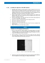
Move the stage in x- and/or y-direction until you see an edge of the mirror. Align the
mirror edge vertically. Position the mirror in such a way that the vertical mirror edge
is more or less in the center of the image. See fig. 4.7.
9.
Set the mirror optics of the GIR objective to the measurement mode (GIR).
Be care-
ful not to displace the mirror lying on the stage unintentionally!
NOTE
Potential risk of damaging the GIR objective
➣
Move the stage upwards carefully. Attention: The working distance of the GIR
objective is only ca. 0.7 mm. Prevent the stage or the sample lying on the stage
from hitting against the bottom side of the GIR objective. Otherwise the mirror
optics of the GIR objective might be damaged.
Figure 4.7:
VIS mode - Image of a vertically aligned mirror edge
Summary of Contents for HYPERION
Page 1: ...HYPERION User Manual I 24319 ...
Page 56: ...54 HYPERION User Manual Bruker Optik GmbH Overview 3 ...
Page 148: ...146 HYPERION User Manual Bruker Optik GmbH Repair and Maintenance 6 ...
Page 168: ...166 HYPERION User Manual Bruker Optik GmbH Specifications A ...
Page 172: ...170 HYPERION User Manual Bruker Optik GmbH Measurement parameters B ...
Page 174: ...172 HYPERION User Manual Bruker Optik GmbH Spare parts and consumables C ...
Page 175: ...173 Bruker Optik GmbH HYPERION User Manual D System diagram ...
Page 176: ...174 HYPERION User Manual Bruker Optik GmbH System diagram D ...


