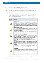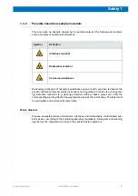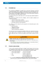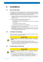
15
Bruker Optik GmbH
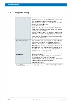
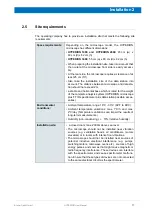
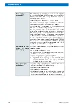
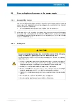
HYPERION User Manual
Installation 2
2.7
Cable connections
In case you intend to relocate the analysis system, this section provides information
about the cable connections. For connecting the data station, monitor etc., refer to the
corresponding computer manual.
2.7.1
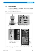
Overview of the connection sockets
Microscope rear side - total view
A
C
D
E
F
B
Microscope rear side - detail view
Spectrometer rear side - detail view
(For example purposes, it is a spectrome-
ter of the TENSOR series.)
Rear side of the supplied PCs
Figure 2.1:
Relevant connection sockets at the microscope (upper images), spectrometer (lower left image) and PC
(lower right image)
I
J
K
L
H
G
Summary of Contents for HYPERION
Page 1: ...HYPERION User Manual I 24319 ...
Page 56: ...54 HYPERION User Manual Bruker Optik GmbH Overview 3 ...
Page 148: ...146 HYPERION User Manual Bruker Optik GmbH Repair and Maintenance 6 ...
Page 168: ...166 HYPERION User Manual Bruker Optik GmbH Specifications A ...
Page 172: ...170 HYPERION User Manual Bruker Optik GmbH Measurement parameters B ...
Page 174: ...172 HYPERION User Manual Bruker Optik GmbH Spare parts and consumables C ...
Page 175: ...173 Bruker Optik GmbH HYPERION User Manual D System diagram ...
Page 176: ...174 HYPERION User Manual Bruker Optik GmbH System diagram D ...

