BSVT Introduction & Configurations
122 / 234
H172203_1_001
12.2
BSVT Hardware
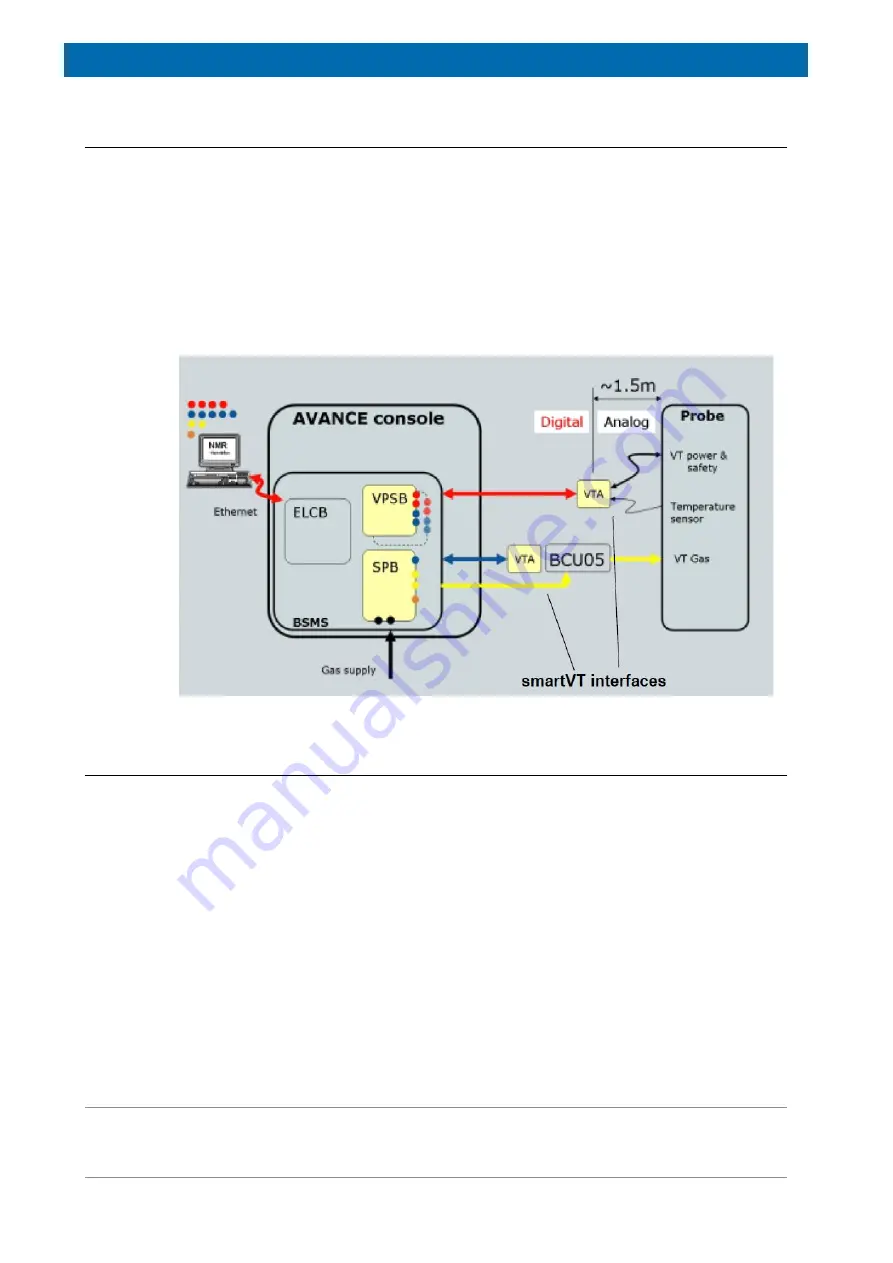
The VT system consists of the following hardware:
• Sensor & Pneumatics Board (SPB or SPB-E) always required.
• Variable Power Supply Boards (VPSB-DC or VPDB-DC-E) only required for VT option.
• VT Interfaces (several styles) only required for VT option.
2
For existing probes and existing VT accessories the corresponding VT interfaces must be
ordered separately. When ordering new probes and VT accessories the VT interfaces are
included if required.
These units are controlled by the BSMS/2 ELCB and are therefore fully integrated into the
well-known Ethernet based communication concept including the web-based service access.
Figure 12.2: BSVT – Open/Digital VT Architecture
12.3
BSVT Software and Features
The BSVT is fully supported with TopSpin 3.0 or later by using an attractive and modern VT
panel for easy user control, monitoring, configuration and other VT specific operation.
• Full client/server architecture via ELCB (Ethernet).
• Modern Topspin control with JAVA operated GUI.
• VT accessories (e.g. LN2 Exchanger, BVTE, BCU-05) are fully supported.
• Optimum performance is provided with basic configuration (no BTO-2000 required).
• Built-in gas flow control and supervision.
• Expandable in future due to modular concept (e.g. easy upgrade for Flow NMR probe).
• Up to 4 heater channels and total 9 temperature sensors channels supported.
• Plug & play operation.
• Integrated flush gas and shim cooling connections.
• No console interaction anymore during normal use (e.g. sensor style change).
2
Mainly for interfacing existing VT accessories and NMR probes (important to check with console ex-
changes to have appropriate VT adapter!)
Summary of Contents for NMR AV4 BSMS System
Page 1: ...BSMS System for AVANCE NEO User Manual Version 001 Innovation with Integrity NMR...
Page 10: ...Contents x H172203_1_001...
Page 22: ...Safety 22 234 H172203_1_001...
Page 26: ...Transport Packaging and Storage 26 234 H172203_1_001...
Page 42: ...Chassis Mainframe 42 234 H172203_1_001...
Page 46: ...Fan Tray 46 234 H172203_1_001...
Page 55: ...ELCB H172203_1_001 55 234 Figure 8 1 ELCB Front Panel with LED s and Connectors...
Page 69: ...ELCB H172203_1_001 69 234 Figure 8 13 Lock RF Boards Diagnostics...
Page 70: ...ELCB 70 234 H172203_1_001...
Page 120: ...L TRX L 19F 120 234 H172203_1_001...
Page 148: ...BSVT Concept 148 234 H172203_1_001...
Page 166: ...SPB 166 234 H172203_1_001...
Page 172: ...VPSB DC and VPSB DC E 172 234 H172203_1_001 Figure 15 3 Block Diagram of the VPSB DC E...
Page 180: ...VPSB DC and VPSB DC E 180 234 H172203_1_001...
Page 187: ...VTA H172203_1_001 187 234 Figure 16 1 VTA Cable Connectors...
Page 193: ...VTA H172203_1_001 193 234 16 7 Ordering Information See Basic BSVT Configuration 124...
Page 194: ...VTA 194 234 H172203_1_001...
Page 200: ...Nitrogen Level Sensor 200 234 H172203_1_001...
Page 204: ...Radiation Shield Temperature Monitoring MAG RS 204 234 H172203_1_001...
Page 208: ...Installation and Initial Commissioning 208 234 H172203_1_001...
Page 210: ...Operation 210 234 H172203_1_001...
Page 216: ...Replacement of Parts 216 234 H172203_1_001...
Page 222: ...Contact 222 234 H172203_1_001...
Page 226: ...List of Figures 226 234 H172203_1_001...
Page 229: ...Glossary H172203_1_001 229 234 Glossary...
Page 230: ...Glossary 230 234 H172203_1_001...
Page 232: ...Index 232 234 H172203_1_001...
Page 233: ...H172203_1_001 233 234...
Page 234: ...Bruker Corporation info bruker com www bruker com Order No H172203...


