BSVT Concept
146 / 234
H172203_1_001
13.3.2
MAS Probes with Tempered Bearing Gas (VTN / WVT)
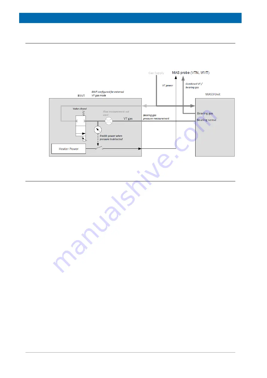
Some MAS probes have no specific VT gas channel, instead they use the MAS bearing gas
for temperature regulation. In these cases, the BSVT can be configured for
External VT Gas
Supply
, where the probe heating is enabled as long as there is enough pressure on the
bearing gas detected. The VT gas valve in the BSVT unit is closed in this operation mode.
Figure 13.4: External VT Gas Supply (e. g. MAS3 Bearing Gas)
13.4
Frequently Asked Questions
• What is the difference between a power channel and an accessory channel?
A power channel provides, in contrast to an accessory channel, a variable power, which
can be controlled (VT power). The basic BSVT configuration provides 2 power channels
and 2 accessory channels. BSVT configurations can be extended up to 4 power channels
and 5 accessory channels.
Both channel types have the 15 pin D-Sub connecter at the user side, but the accessory
channel is connected to the back panel of the NMR cabinet by a smaller RJ45 connecter.
The width of the power channel cable is quite higher than that of an accessory channel.
• What happens if a probe is connected to an accessory channel?
A probe can be connected via the appropriate VT adapter to any channel. However, if the
channel does not provide VT power then the VT temperature of the probe cannot be
controlled and stabilized. Nevertheless, the temperature measurements are transferred in
regular intervals to the BSVT unit and displayed within the Topspin GUI.
• What could be the reason for inoperable devices?
It can happen that a power device connected to a power channel cannot be operated and
is marked as inoperable in the Topspin GUI. Either a heater or sensor cable between VT
adapter and heating device (e. g. probe) is not connected. Or the device (VT adapter) has
been added while the BSVT was in operation. In that case, the BSVT stays in operation
mode (if there is no device removed that was involved in temperature regulation), the new
devices are integrated into the BSVT temperature control as soon as the temperature
regulation is switched off next time.
Summary of Contents for NMR AV4 BSMS System
Page 1: ...BSMS System for AVANCE NEO User Manual Version 001 Innovation with Integrity NMR...
Page 10: ...Contents x H172203_1_001...
Page 22: ...Safety 22 234 H172203_1_001...
Page 26: ...Transport Packaging and Storage 26 234 H172203_1_001...
Page 42: ...Chassis Mainframe 42 234 H172203_1_001...
Page 46: ...Fan Tray 46 234 H172203_1_001...
Page 55: ...ELCB H172203_1_001 55 234 Figure 8 1 ELCB Front Panel with LED s and Connectors...
Page 69: ...ELCB H172203_1_001 69 234 Figure 8 13 Lock RF Boards Diagnostics...
Page 70: ...ELCB 70 234 H172203_1_001...
Page 120: ...L TRX L 19F 120 234 H172203_1_001...
Page 148: ...BSVT Concept 148 234 H172203_1_001...
Page 166: ...SPB 166 234 H172203_1_001...
Page 172: ...VPSB DC and VPSB DC E 172 234 H172203_1_001 Figure 15 3 Block Diagram of the VPSB DC E...
Page 180: ...VPSB DC and VPSB DC E 180 234 H172203_1_001...
Page 187: ...VTA H172203_1_001 187 234 Figure 16 1 VTA Cable Connectors...
Page 193: ...VTA H172203_1_001 193 234 16 7 Ordering Information See Basic BSVT Configuration 124...
Page 194: ...VTA 194 234 H172203_1_001...
Page 200: ...Nitrogen Level Sensor 200 234 H172203_1_001...
Page 204: ...Radiation Shield Temperature Monitoring MAG RS 204 234 H172203_1_001...
Page 208: ...Installation and Initial Commissioning 208 234 H172203_1_001...
Page 210: ...Operation 210 234 H172203_1_001...
Page 216: ...Replacement of Parts 216 234 H172203_1_001...
Page 222: ...Contact 222 234 H172203_1_001...
Page 226: ...List of Figures 226 234 H172203_1_001...
Page 229: ...Glossary H172203_1_001 229 234 Glossary...
Page 230: ...Glossary 230 234 H172203_1_001...
Page 232: ...Index 232 234 H172203_1_001...
Page 233: ...H172203_1_001 233 234...
Page 234: ...Bruker Corporation info bruker com www bruker com Order No H172203...


