SCB20
H172203_1_001
77 / 234
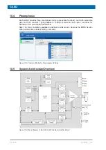
Downloading of new BOSS files and setting up of specific parameters for the shim functions
(e. g. pulse polarity for RCB) can be done under
Shim Configuration
.
The example shows a BSMS with two SCB20, therefore there are two according menu points
for low level service functions, one for each board, providing diagnostic information in case of
problems.
A further option for debugging the shim functions is the
Shim Current Tool
, which provides
access to all currents - it is possible to define the strength of the currents individually, and to
read the resulting current measurements on the display.
There is additionally a
Shim Power Supply Information
, which displays information about
the current consumption due to the currently defined shim settings.
9.5.2
Setup the Shim Functions
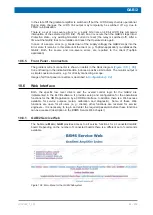
Figure 9.5: Setup and Configuration of the Shim Subsystem
1
The currently loaded BOSS file name is displayed here. If the connected Shim
System is a BOSS1 then the name of the predefined data set
BOSS1
is
displayed. If there is no valid BOSS data available for the connected Shim
System, then this is indicated by
No BOSS Matrix loaded!
. The file names for
non-BOSS1 Shim Systems start with the Shim System ID (see point 3), with two
characters appended - the first character specifies the frequency range for
BOSS3 and BOSS-WB systems - character
a
means no specific range. The
second character indicates the version of the BOSS file (ascending for higher
versions).
Summary of Contents for NMR AV4 BSMS System
Page 1: ...BSMS System for AVANCE NEO User Manual Version 001 Innovation with Integrity NMR...
Page 10: ...Contents x H172203_1_001...
Page 22: ...Safety 22 234 H172203_1_001...
Page 26: ...Transport Packaging and Storage 26 234 H172203_1_001...
Page 42: ...Chassis Mainframe 42 234 H172203_1_001...
Page 46: ...Fan Tray 46 234 H172203_1_001...
Page 55: ...ELCB H172203_1_001 55 234 Figure 8 1 ELCB Front Panel with LED s and Connectors...
Page 69: ...ELCB H172203_1_001 69 234 Figure 8 13 Lock RF Boards Diagnostics...
Page 70: ...ELCB 70 234 H172203_1_001...
Page 120: ...L TRX L 19F 120 234 H172203_1_001...
Page 148: ...BSVT Concept 148 234 H172203_1_001...
Page 166: ...SPB 166 234 H172203_1_001...
Page 172: ...VPSB DC and VPSB DC E 172 234 H172203_1_001 Figure 15 3 Block Diagram of the VPSB DC E...
Page 180: ...VPSB DC and VPSB DC E 180 234 H172203_1_001...
Page 187: ...VTA H172203_1_001 187 234 Figure 16 1 VTA Cable Connectors...
Page 193: ...VTA H172203_1_001 193 234 16 7 Ordering Information See Basic BSVT Configuration 124...
Page 194: ...VTA 194 234 H172203_1_001...
Page 200: ...Nitrogen Level Sensor 200 234 H172203_1_001...
Page 204: ...Radiation Shield Temperature Monitoring MAG RS 204 234 H172203_1_001...
Page 208: ...Installation and Initial Commissioning 208 234 H172203_1_001...
Page 210: ...Operation 210 234 H172203_1_001...
Page 216: ...Replacement of Parts 216 234 H172203_1_001...
Page 222: ...Contact 222 234 H172203_1_001...
Page 226: ...List of Figures 226 234 H172203_1_001...
Page 229: ...Glossary H172203_1_001 229 234 Glossary...
Page 230: ...Glossary 230 234 H172203_1_001...
Page 232: ...Index 232 234 H172203_1_001...
Page 233: ...H172203_1_001 233 234...
Page 234: ...Bruker Corporation info bruker com www bruker com Order No H172203...


