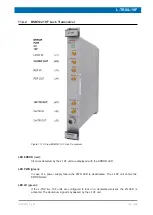
L-TRX/L-19F
98 / 234
H172203_1_001
Product Firmware
The L-TRX / L-19F firmware packages are field-upgradable via ELCB. The factory con-
figuration is stored on-board in a write protected memory section. The user can always reload
the factory firmware.
Fluorine Lock
The former fluorine lock option piggy modules have been integrated into a dedicated
deuterium to fluorine up and down converter unit (L-19F). While locking on a deuterated
solvent, the L-19F unit is bypassed. Whereas the L-19F unit translates the deuterium lock
signal into the fluorine lock signal, while locking on samples containing fluorine as lock
solvent.
11.2.2
Protection
Power Supply and Reference Clock Supervision
All power supply voltages and the necessary reference clocks are internally monitored. In
case of a failure the PWR/CLK LED (L-TRX) or the PWR LED (L-19F) are deactivated and an
appropriate error message is generated (if still possible).
Over-Temperature Protection (L-TRX only)
The power amplifier and board temperature are monitored on-board. The ELCB can access
the relevant sensors and act accordingly.
If the temperature reaches the limit of safe operation, the power amplifier is switched off
immediately without intervention of the ELCB. The L-TRX enters the ERROR state. An error
message is sent to TopSpin. See
After regaining normal temperature conditions, the L-TRX reverts to the operating mode prior
to the error.
Over-Current Protection (L-TRX only)
If the power amplifier drain current exceeds the limit of safe operation, it is switched off and
the L-TRX enters the ERROR state. An error message is sent to TopSpin. See
11.2.3
Internal Diagnostics
The L-TRX has extensive internal diagnostic functions which can be accessed via the Service
Web. See
.
Many of the diagnostics are performed automatically during power-up and assessed by the
ELCB. If a failure occurs, an appropriate error message is generated.
Due to the low complexity of the L-19F unit, the unit does not have any dedicated diagnostic
functions.
Summary of Contents for NMR AV4 BSMS System
Page 1: ...BSMS System for AVANCE NEO User Manual Version 001 Innovation with Integrity NMR...
Page 10: ...Contents x H172203_1_001...
Page 22: ...Safety 22 234 H172203_1_001...
Page 26: ...Transport Packaging and Storage 26 234 H172203_1_001...
Page 42: ...Chassis Mainframe 42 234 H172203_1_001...
Page 46: ...Fan Tray 46 234 H172203_1_001...
Page 55: ...ELCB H172203_1_001 55 234 Figure 8 1 ELCB Front Panel with LED s and Connectors...
Page 69: ...ELCB H172203_1_001 69 234 Figure 8 13 Lock RF Boards Diagnostics...
Page 70: ...ELCB 70 234 H172203_1_001...
Page 120: ...L TRX L 19F 120 234 H172203_1_001...
Page 148: ...BSVT Concept 148 234 H172203_1_001...
Page 166: ...SPB 166 234 H172203_1_001...
Page 172: ...VPSB DC and VPSB DC E 172 234 H172203_1_001 Figure 15 3 Block Diagram of the VPSB DC E...
Page 180: ...VPSB DC and VPSB DC E 180 234 H172203_1_001...
Page 187: ...VTA H172203_1_001 187 234 Figure 16 1 VTA Cable Connectors...
Page 193: ...VTA H172203_1_001 193 234 16 7 Ordering Information See Basic BSVT Configuration 124...
Page 194: ...VTA 194 234 H172203_1_001...
Page 200: ...Nitrogen Level Sensor 200 234 H172203_1_001...
Page 204: ...Radiation Shield Temperature Monitoring MAG RS 204 234 H172203_1_001...
Page 208: ...Installation and Initial Commissioning 208 234 H172203_1_001...
Page 210: ...Operation 210 234 H172203_1_001...
Page 216: ...Replacement of Parts 216 234 H172203_1_001...
Page 222: ...Contact 222 234 H172203_1_001...
Page 226: ...List of Figures 226 234 H172203_1_001...
Page 229: ...Glossary H172203_1_001 229 234 Glossary...
Page 230: ...Glossary 230 234 H172203_1_001...
Page 232: ...Index 232 234 H172203_1_001...
Page 233: ...H172203_1_001 233 234...
Page 234: ...Bruker Corporation info bruker com www bruker com Order No H172203...


