AV4 BSMS System
28 / 234
H172203_1_001
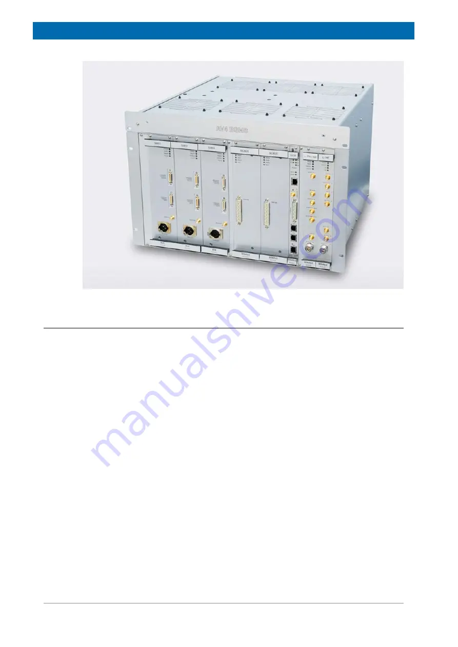
Figure 4.1: AV4 BSMS Chassis with 3-Axis Gradient for AVANCE NEO
4.1.1
Subunits in the AV4 BSMS
Shim
The SCB20 (Shim Current Board) provides the required precision for all existing types of
shim systems and can therefore replace any variant of former SCB7 and SCB13.
Connectivity to the different Shim Systems is provided by a set of various adapters. For
BOSS1 Shim Systems, one SCB20 is sufficient, whereas two SCB20 cover the whole range
of currently available Shim Systems, including BOSS1 (the connector of the left hand side
SCB20 remains open in that case).
Lock
The ELCB (Ethernet based Lock Control Board) incorporates the lock functions like the lock
control algorithm and the H0 current source. In addition, this ELCB acts as communication
gateway between the workstation and the various subunits inside of the BSMS. The BSMS
can be directly accessed with a standard Internet browser via HTTP protocol or allows
hardware independent communication with TopSpin 2.0 and higher by using a CORBA
interface.
The highly integrated Lock RF unit L-TRX provides a direct digital RF transmitter and receiver
and includes all what is necessary to allow gradient shimming on 2H. For locking on 19F
solvents, there is a separate 19F Lock Transceiver available. The L-TRX is frequency
specific, whereas the 19F Lock Transceiver covers a wide frequency range.
Summary of Contents for NMR AV4 BSMS System
Page 1: ...BSMS System for AVANCE NEO User Manual Version 001 Innovation with Integrity NMR...
Page 10: ...Contents x H172203_1_001...
Page 22: ...Safety 22 234 H172203_1_001...
Page 26: ...Transport Packaging and Storage 26 234 H172203_1_001...
Page 42: ...Chassis Mainframe 42 234 H172203_1_001...
Page 46: ...Fan Tray 46 234 H172203_1_001...
Page 55: ...ELCB H172203_1_001 55 234 Figure 8 1 ELCB Front Panel with LED s and Connectors...
Page 69: ...ELCB H172203_1_001 69 234 Figure 8 13 Lock RF Boards Diagnostics...
Page 70: ...ELCB 70 234 H172203_1_001...
Page 120: ...L TRX L 19F 120 234 H172203_1_001...
Page 148: ...BSVT Concept 148 234 H172203_1_001...
Page 166: ...SPB 166 234 H172203_1_001...
Page 172: ...VPSB DC and VPSB DC E 172 234 H172203_1_001 Figure 15 3 Block Diagram of the VPSB DC E...
Page 180: ...VPSB DC and VPSB DC E 180 234 H172203_1_001...
Page 187: ...VTA H172203_1_001 187 234 Figure 16 1 VTA Cable Connectors...
Page 193: ...VTA H172203_1_001 193 234 16 7 Ordering Information See Basic BSVT Configuration 124...
Page 194: ...VTA 194 234 H172203_1_001...
Page 200: ...Nitrogen Level Sensor 200 234 H172203_1_001...
Page 204: ...Radiation Shield Temperature Monitoring MAG RS 204 234 H172203_1_001...
Page 208: ...Installation and Initial Commissioning 208 234 H172203_1_001...
Page 210: ...Operation 210 234 H172203_1_001...
Page 216: ...Replacement of Parts 216 234 H172203_1_001...
Page 222: ...Contact 222 234 H172203_1_001...
Page 226: ...List of Figures 226 234 H172203_1_001...
Page 229: ...Glossary H172203_1_001 229 234 Glossary...
Page 230: ...Glossary 230 234 H172203_1_001...
Page 232: ...Index 232 234 H172203_1_001...
Page 233: ...H172203_1_001 233 234...
Page 234: ...Bruker Corporation info bruker com www bruker com Order No H172203...


