AV4 BSMS System
H172203_1_001
29 / 234
Gradient amplifier
With the introduction of the AVANCE NEO in 2017, the BSMS/2 GAB/2 has been replaced
with the AV4 GAB/2. In addition to the built-in pre-emphasis capability, which was already
available on its predecessor, the new model provides daisy chainable control (LVDS48).
Together with the extendable power supply, this allows a modular gradient amplifier
configuration in a single AV4 BSMS chassis driving up to three gradient coils (XYZ), and it is
possible to extend the gradient control chain for external gradient amplifiers (e. g. for micro
imaging).
Variable temperature control, sample handling and level monitoring
In 2010 there has been made a higher integration of the pneumatic functions for sample
handling (lift, spin), the variable temperature control (power supply and various sensor
interfacing, gas flow controls) and fill level monitoring for the magnet (helium and nitrogen
level). These functions are now provided by the SPB / SPB-E and VPSB boards, which
replace the former SLCB and PNK, the built in BVT3200 (with corresponding power supply)
or any of the stand alone BVT3000 variants.
In 2011 a digital nitrogen level sensor has been introduced together with the ASCEND family
of magnet systems.
With the introduction of the AVANCE NEO in 2017, the BSMS/2 VPSB was replaced with the
AV4 VPSB-DC or the AV4 VPSB-DC-E. Both boards take their power and control signals
directly from the backplane, no separate mains power supply and LVDS control cable are
necessary anymore.
All configurations with Standard Bore (SB) can be covered with the AV4 VPSB-DC, whereas
Wide Bore (WB) systems are equipped with an AV4 VPSB-DC-E, which includes the booster
functionality and makes the booster BVTB3500 obsolete.
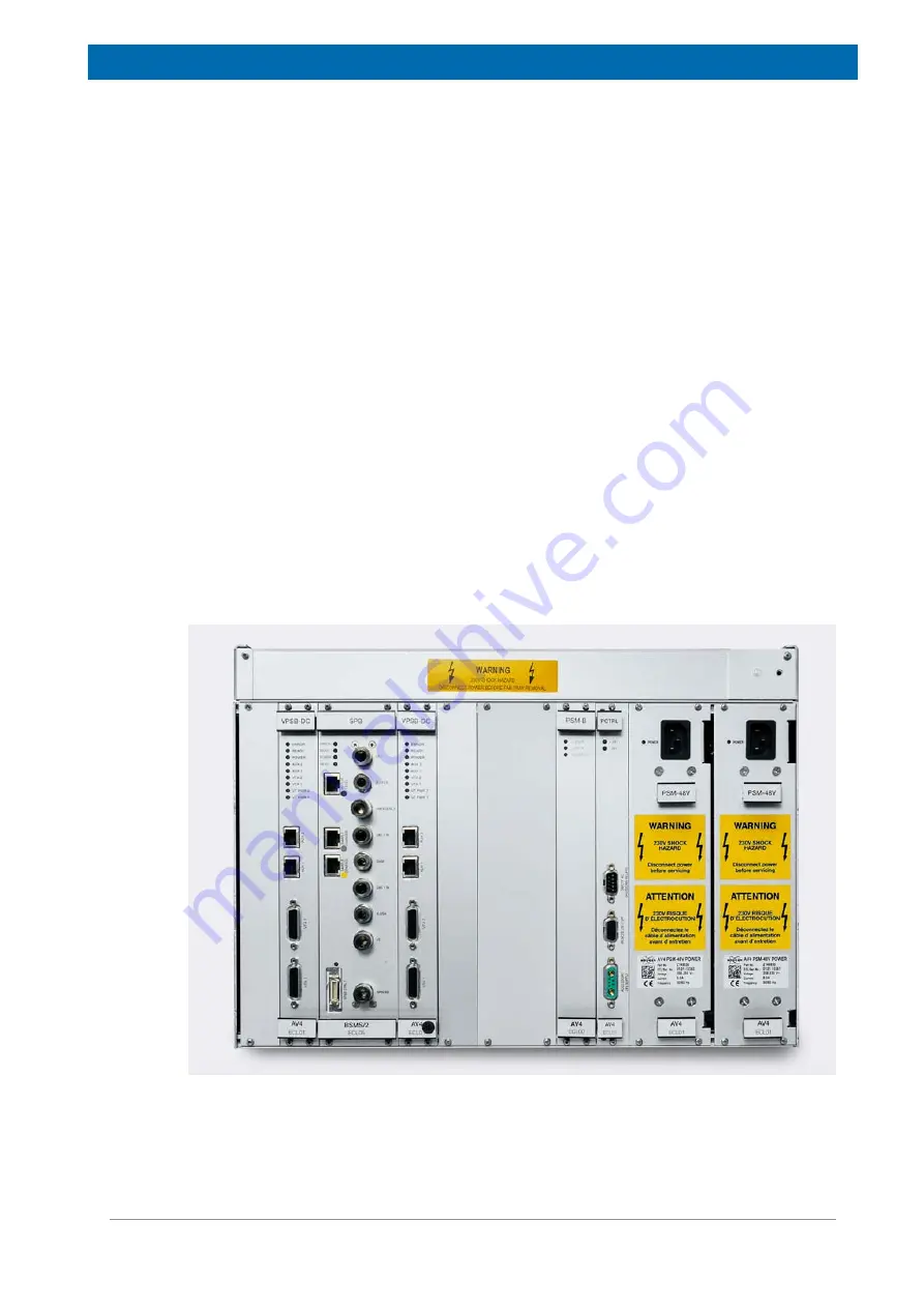
Figure 4.2: AV4 BSMS Chassis Rear View
Summary of Contents for NMR AV4 BSMS System
Page 1: ...BSMS System for AVANCE NEO User Manual Version 001 Innovation with Integrity NMR...
Page 10: ...Contents x H172203_1_001...
Page 22: ...Safety 22 234 H172203_1_001...
Page 26: ...Transport Packaging and Storage 26 234 H172203_1_001...
Page 42: ...Chassis Mainframe 42 234 H172203_1_001...
Page 46: ...Fan Tray 46 234 H172203_1_001...
Page 55: ...ELCB H172203_1_001 55 234 Figure 8 1 ELCB Front Panel with LED s and Connectors...
Page 69: ...ELCB H172203_1_001 69 234 Figure 8 13 Lock RF Boards Diagnostics...
Page 70: ...ELCB 70 234 H172203_1_001...
Page 120: ...L TRX L 19F 120 234 H172203_1_001...
Page 148: ...BSVT Concept 148 234 H172203_1_001...
Page 166: ...SPB 166 234 H172203_1_001...
Page 172: ...VPSB DC and VPSB DC E 172 234 H172203_1_001 Figure 15 3 Block Diagram of the VPSB DC E...
Page 180: ...VPSB DC and VPSB DC E 180 234 H172203_1_001...
Page 187: ...VTA H172203_1_001 187 234 Figure 16 1 VTA Cable Connectors...
Page 193: ...VTA H172203_1_001 193 234 16 7 Ordering Information See Basic BSVT Configuration 124...
Page 194: ...VTA 194 234 H172203_1_001...
Page 200: ...Nitrogen Level Sensor 200 234 H172203_1_001...
Page 204: ...Radiation Shield Temperature Monitoring MAG RS 204 234 H172203_1_001...
Page 208: ...Installation and Initial Commissioning 208 234 H172203_1_001...
Page 210: ...Operation 210 234 H172203_1_001...
Page 216: ...Replacement of Parts 216 234 H172203_1_001...
Page 222: ...Contact 222 234 H172203_1_001...
Page 226: ...List of Figures 226 234 H172203_1_001...
Page 229: ...Glossary H172203_1_001 229 234 Glossary...
Page 230: ...Glossary 230 234 H172203_1_001...
Page 232: ...Index 232 234 H172203_1_001...
Page 233: ...H172203_1_001 233 234...
Page 234: ...Bruker Corporation info bruker com www bruker com Order No H172203...


