SCB20
80 / 234
H172203_1_001
For the case that there is a problem regarding the shim function (e. g. if there is an error
message issued when the user wants to set or modify the value of a shim), it is possible to
run the built-in self-test on each SCB20 board in order to verify that the SCB20 boards are in
a correct state.
The power dissipation in the Shim Coil and the power consumption is displayed as additional
information. In case of a failed attempt to set or modify a shim value, it is recommended to
check if the power limit of the Shim Coil is reached or if the power supply is at its limit. It may
be necessary to reset manually all currents to zero, which can be easily done by the
Shim
Current Tool
.
Additional information about the consumed power and remaining margin can be retrieved
under
Main
|
Shim
|
Shim Power Supply Information
.
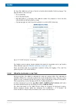
Figure 9.8: SCB20 Measurement Functions Web Page
9.5.6
No BOSS File for Currently Installed Shim System?
The procedure given here may be useful in case of an error message
Error: Shim: Cannot
initialize Shim System .. with BOSS file ...
or if you cannot find an appropriate BOSS matrix
file for the Shim System type that is indicated by the BSMS Service Web. It may be
necessary to apply the procedure iteratively.
Summary of Contents for NMR AV4 BSMS System
Page 1: ...BSMS System for AVANCE NEO User Manual Version 001 Innovation with Integrity NMR...
Page 10: ...Contents x H172203_1_001...
Page 22: ...Safety 22 234 H172203_1_001...
Page 26: ...Transport Packaging and Storage 26 234 H172203_1_001...
Page 42: ...Chassis Mainframe 42 234 H172203_1_001...
Page 46: ...Fan Tray 46 234 H172203_1_001...
Page 55: ...ELCB H172203_1_001 55 234 Figure 8 1 ELCB Front Panel with LED s and Connectors...
Page 69: ...ELCB H172203_1_001 69 234 Figure 8 13 Lock RF Boards Diagnostics...
Page 70: ...ELCB 70 234 H172203_1_001...
Page 120: ...L TRX L 19F 120 234 H172203_1_001...
Page 148: ...BSVT Concept 148 234 H172203_1_001...
Page 166: ...SPB 166 234 H172203_1_001...
Page 172: ...VPSB DC and VPSB DC E 172 234 H172203_1_001 Figure 15 3 Block Diagram of the VPSB DC E...
Page 180: ...VPSB DC and VPSB DC E 180 234 H172203_1_001...
Page 187: ...VTA H172203_1_001 187 234 Figure 16 1 VTA Cable Connectors...
Page 193: ...VTA H172203_1_001 193 234 16 7 Ordering Information See Basic BSVT Configuration 124...
Page 194: ...VTA 194 234 H172203_1_001...
Page 200: ...Nitrogen Level Sensor 200 234 H172203_1_001...
Page 204: ...Radiation Shield Temperature Monitoring MAG RS 204 234 H172203_1_001...
Page 208: ...Installation and Initial Commissioning 208 234 H172203_1_001...
Page 210: ...Operation 210 234 H172203_1_001...
Page 216: ...Replacement of Parts 216 234 H172203_1_001...
Page 222: ...Contact 222 234 H172203_1_001...
Page 226: ...List of Figures 226 234 H172203_1_001...
Page 229: ...Glossary H172203_1_001 229 234 Glossary...
Page 230: ...Glossary 230 234 H172203_1_001...
Page 232: ...Index 232 234 H172203_1_001...
Page 233: ...H172203_1_001 233 234...
Page 234: ...Bruker Corporation info bruker com www bruker com Order No H172203...


