12
©2004,1998 Bruno Independent Living Aids, Inc.®
CRE-2100 NRUL 08-16-2004
INSTALLATION
8.
Install the remaining lower section(s), if applicable, and add clamps as shown on the
installation drawing.
9.
Install the upper rail section(s), adding clamp assemblies with each section.
NOTE: Do not install the end plate and charge bracket at this time.
10.
Position the rail as close to the application drawing measurements as possible.
11.
Secure the rail with one or two screws.
NOTE: You may need to shim the rail to ensure proper placement. For example,
if the rail is leaning forward, shim the front of the clamp until the unit
is level.
****VERY IMPORTANT****
The degree of slope of the rail is critical. To locate the degree at which each rail piece
should be installed, use the ELEVATION VIEW drawings
specific to
your job
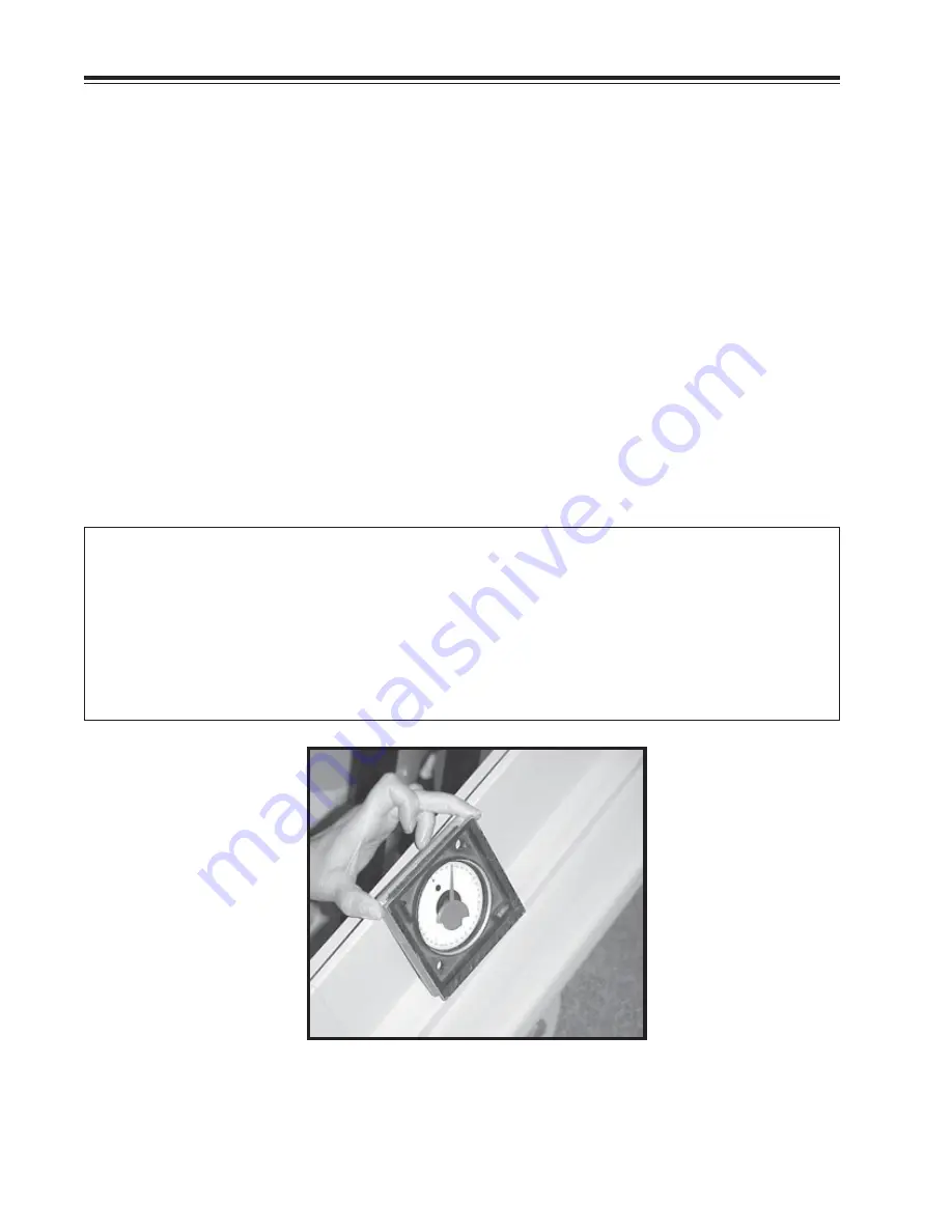
and inserted in this manual. Place the angle finder on the guide strip on the front
of the rail to obtain the
correct angle
.
The
correct angle
should be observed within 1/2 degree, every (2) feet of linear rail travel.
Be sure to check the rail angle every
(2) feet of linear travel.


