Bandit
33
Copyright 6/12
MODEL 200 UC
Consult your engine manual for proper break‑in procedures. Various engines require somewhat different
procedures, but basically the engines need to operate at lower R.P.M.’s and loads for a specific time.
Failure to properly break‑in your engine may result in poor bearing and piston ring surfaces.
The Bandit has only been run for a short time to test proper hydraulic pressures, possible leaks, etc. The
fuel tank will be empty. Fuel is provided through a small auxiliary tank for testing. This immensely helps
maintain safety in our manufacturing facility and while shipping.
Do not let anyone operate or maintain this machine until they have thoroughly read this manual, reviewed
the equipment decals, watched the equipment video, and has been properly trained. You can purchase
additional Bandit manuals, decals and videos for a nominal fee.
Expensive damage to the Bandit will occur if proper preparation is not taken before welding on the machine.
Be sure to disconnect both battery cables and the engine ECM (engine control module) before welding. Follow
the specific Engine MFG. instructions for proper welding and grounding procedures, before attempting to weld
on the machine. If welding on the machine, do not ground the welder through the machine bearings, ground
near work to be performed.
MAINTENANCE SECTION
MAINTENANCE SECTION
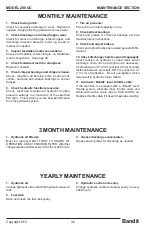
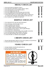
The Bandit is a very simple machine to maintain. If you will follow a regular scheduled preventative
maintenance program, you should have years of trouble free operation.
DANGER
!
NOTICE
NOTICE
NOTICE
NOTICE
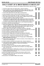
1. Check the safety decals and engine gauges:
Replace any missing or damaged decals and/or
engine gauges.
2.
Check all safety equipment:
Check for proper operation. Repair or replace as
needed. With everything shut down and stopped,
insure last chance cables freely operate feed control
valve.
3. Check entire machine for loose bolts, nuts,
parts, or components:
Check entire machine for any loose parts or
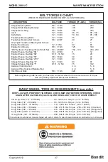
components. Check for loose nuts or bolts. Torque,
tighten, or replace any of the loose components. See
page 37 for specific bolt torques.
4. Check all guards:
Check to make sure all guards are in place and
installed correctly. Make sure they are secure.
5. Check chipper hood hinge:
Make sure the hood hinge operates correctly, and is
lubricated. Must replace hinge if damaged.
6. Checking for foreign objects:
Before opening the hood make sure the clutch is
disengaged, the engine off, the disc/drum lock pin
is installed, battery is disconnected, and also make
sure the ignition key is in your possession. Remove
the hood pin padlock, disconnect the chipper hood
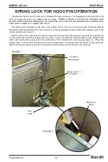
engine disable plug, suppress the spring lock for
hood pin on disc chippers, and then remove the
hood lock pin. Look for any foreign objects inside
the chipper housing or in the knife pockets of the
disc/drum. Remove any foreign objects found.
7. Check chipper disc assembly:
Check for elongated bolt holes, secure welds,
torqued bolts, excessive wear and impact cracks. If a
problem is found contact the chipper manufacturer or
an authorized Bandit dealer. Also check the chipper
housing at this time. Check the chipper base, belly
band, and hoods for wear or damage. Also inspect
the chipper bearings.
DAILY START UP & MAINTENANCE
Before attempting any type of maintenance disengage clutch, turn off engine, wait for the disc/drum to
come to a complete stop, install the disc/drum lock pin, disconnect battery, and make sure the ignition key is
in your possession.
DANGER
!
Summary of Contents for 200 UC
Page 17: ......
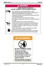
Page 35: ...Bandit 19 Copyright 6 12 MODEL 200 UC DECALS ...
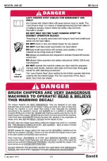
Page 36: ...Bandit 20 Copyright 6 12 MODEL 200 UC DECALS ...
Page 69: ...Bandit 53 Copyright 6 12 MODEL 200 UC HYDRAULIC SECTION HYDRAULIC SECTION ...
Page 126: ...Bandit 110 Copyright 6 12 MODEL 200 UC SERVICE RECORD SERVICE RECORD DATE DESCRIPTION AMOUNT ...

