background image

29

BRIGGS AND STRATTON POWER PRODUCTS GROUP, L.L.C. OWNER WARRANTY POLICY

Effective January 1, 2008 replaces all undated Warranties and all Warranties dated before January 1, 2008

LIMITED WARRANTY

Briggs & Stratton Power Products Group, LLC will repair or replace, free of charge, any part(s) of the product that is defective in material or workmanship or
both. Transportation charges on product submitted for repair or replacement under this warranty must be borne by purchaser. This warranty is effective for
the time periods and subject to the conditions stated below. For warranty service, find the nearest Authorized Service Dealer in our dealer locator map at

THERE IS NO OTHER EXPRESS WARRANTY, IMPLIED WARRANTIES, INCLUDING THOSE OF MERCHANTABILITY AND FITNESS FOR A PARTICU-
LAR PURPOSE, ARE LIMITED TO ONE YEAR FROM PURCHASE, OR TO THE EXTENT PERMITTED BY LAW. ANY AND ALL IMPLIED WARRANTIES
ARE EXCLUDED. LIABILITY FOR INCIDENTAL OR CONSEQUENTIAL DAMAGES ARE EXCLUDED TO THE EXTENT EXCLUSION IS PERMITTED BY
LAW. Some states or countries do not allow limitations on how long an implied warranty lasts, and some states or countries do not allow the exclusion or
limitation of incidental or consequential damages, so the above limitation and exclusion may not apply to you. This warranty gives you specific legal rights
and you may also have other rights which vary from state to state or country to country.

WARRANTY TERMS

Consumer 

Commercial

Brand / Unit

U


se

U


se


Dual Stage Snow Thrower . . . . . . . . . . . . . . . . . . . . . . . . . .   2 years . . . . . . . . . . . . . . . . . . . . . . . .  90 Days    

The warranty period begins on the date of purchase by the first retail consumer or commercial end user, and continues for the period of time stated above.
“Consumer use” means personal residential household use by a retail consumer. “Commercial use” means all other uses, including use for commercial, in-
come producing or rental purposes. Once product has experienced commercial use, it shall thereafter be considered as commercial use for purposes of
this warranty.

No warranty registration is necessary to obtain warranty on 

BRUTE

branded products. Save your proof of purchase receipt. If you do not provide proof

of the initial purchase date at the time warranty service is requested, the manufacturing date of the product will be used to determine the warranty.

ABOUT YOUR WARRANTY

We welcome warranty repair and apologize to you for being inconvenienced. Any Authorized Service Dealer may perform warranty repairs. Most warranty
repairs are handled routinely, but sometimes requests for warranty service may not be appropriate. For example, warranty service would not apply to the
product if damage occurred because of misuse, lack of routine maintenance, shipping, handling, warehousing or improper installation. Similarly, the war-
ranty is void if the serial number on the product has been removed or the product has been altered or modified.

This warranty covers product related defective material and/or workmanship only. To avoid misunderstanding which might occur between the customer and
the Dealer, listed below are some of the causes of product failure that the warranty does not cover.

Normal Wear: Small Engine Powered Equipment, like all mechanical devices, needs periodic parts and service to perform well. Warranty does not
cover repair when normal use has exhausted the life of the product or part.

Installation: This warranty does not apply to product that has been subjected to improper or unauthorized installation, alteration or modification. Nor 
installations that prevent starting cause unsatisfactory engine performance.

Improper Maintenance: The life of this product depends upon the conditions under which it operates, and the care it receives. Recommended mainte-
nance and adjustment intervals are stated in the Operator’s Manual. Often product, such as tillers, edgers, rotary mowers, are used in dusty or dirty 
conditions, which can cause what appears to be premature wear. Such wear, when caused by dirt, dust, or other abrasive material entering the prod-
uct because of improper maintenance is not covered by warranty. The warranty will not cover repairs due to problems caused by replacement parts 
that are not original manufactured part(s).

Incorrect and/or Insufficient Fuel or Lubrication: This warranty does not cover damage caused by the use of stale fuel, or altered gasoline. Damage to 
engine or engine components i.e., combustion chamber, valves, valve seats, valve guides, burned starter motor windings caused by use of alternate 
fuels such as liquefied petroleum, natural gas, are not covered unless engine is certified for this operation. Parts which are scored or broken because 
product was operated with insufficient, contaminated or incorrect grade of lubricating oil as well as product components damaged due to lack of lubri-
cation are not covered.

Operational Misuse: Proper operation of the product is stated in the Operator’s Manual. Product damaged by overspeeding, overheating, or operation 
in a confined area without sufficient ventilation. Product broken by excessive vibration caused by a loose engine mounting, loose or unbalanced 
blades, impellers, overspeeding, or bent crankshaft due to striking of solid object. Damage or malfunctions resulting from accidents, abuse, or im-
proper servicing or freezing or chemical deterioration, as well as operating in excess of recommended capacities as outlined in the Operator’s Manual
are not covered.

Routine Tune-Up, Wear Items, or Adjustments: This warranty excludes wear items such as oil, belts, blades, o-rings, filters, etc.

Other Exclusions: Repair or adjustments for part(s) that are not manufactured by Briggs & Stratton Corporation, are not covered, see warranty for re-
spective manufacturers. This warranty excludes failures due to acts of God and other major forceful events beyond the manufacturer’s control.
Also excluded are used, reconditioned, and demonstration products.

Warranty service is available only through Authorized Service Dealers. Locate your nearest dealer in our locator map at 

www.brutepower.com.

www.brutepower.com.

WARRANTIES

Not 

for  

Reproduction

Summary of Contents for 1695724

Page 1: ...Manual Part No 1738019 Revision B Rev Date 04 2009 Operator s Manual Walk Behind Snow Thrower Mfg No Description 1695724 Dual Stage Snow Thrower 11 5 TP 27 Inch N o t f o r R e p r o d u c t i o n...

Page 2: ...completely Save these instructions for future reference Where to Find Us You never have to look far to find Briggs Stratton support and service for your snow thrower Consult your Yellow Pages There ar...

Page 3: ...TIONS 18 AFTER EACH USE 18 LUBRICATE AUGER GEAR BOX 19 LUBRICATE AUGER SHAFT FITTINGS 19 CHECK LUBRICATE FREE HAND LINKAGE 19 LUBRICATE CHUTE ROTATION GEAR 19 ADUST THE DRAG ON THE CHUTE ROTATION 19 E...

Page 4: ...injury Operator s Manual Read and understand before performing any activity or running snow thrower Rotating Impeller Keep a Safe Distance from Snow Thrower Rotating Auger Rotating Gears Never Reach i...

Page 5: ...on equipment damage and voiding of the product warranty DANGER Read understand and follow all the instructions on the snow thrower and in the operator s manual before operating this unit Failure to ob...

Page 6: ...s can cause a fire or explosion which will result in severe burns or death Fuel Handling Keep the area of operation clear of all persons particularly small children and pets Thoroughly inspect the are...

Page 7: ...he auger Use extreme caution when operating on or crossing gravel drives walks or roads Adjust the collector housing height to clear gravel or crushed rock surface Never operate the snow thrower near...

Page 8: ...commended by the factory WARNING This snow thrower must be properly maintained to ensure safe operation and performance Failure to observe the safety instructions in this manual could result in death...

Page 9: ...ION REGULATIONS FOR SMALL OFF ROAD ENGINES REFER TO OWNER S MANUAL FOR MAINTENANCE SPECIFICATIONS ADJUSTMENTS AND EMISSIONS DURABILITY INFORMATION EPA EMISSIONS COMPLIANCE PERIOD CATEGORY X CA COMPLIA...

Page 10: ...tor manifold to ensure fast starts in cool weather D Safety Key Must be inserted to start engine Pull out to stop Do not turn safety key E Starter Handle Starts the engine manually F ON OFF Switch Eng...

Page 11: ...nge direction of the snow discharge Turn han dle clockwise to turn chute to right Turn handle counterclockwise to turn chute to left Snow Thrower Controls Figure 3 F Skid Shoe Used to adjust ground cl...

Page 12: ...n the tires with an accurate gauge see Figure 4 CAUTION Avoid Injury Explosive separation of tire and rim parts is possible when they are serviced incorrectly Do not attempt to mount a tire without th...

Page 13: ...s shields in place Never direct discharge towards windows or allow bystanders near machine while engine is running Stop the engine whenever leaving the operating position Disconnect spark plug before...

Page 14: ...ck the oil NOTE Do not check the level of the oil while the engine runs 5 If necessary add oil until the oil reaches the FULL mark on the oil fill cap dipstick Do not add too much oil 6 Tighten the oi...

Page 15: ...e on AC house hold current The power cord must be properly grounded at all times to avoid the possibility of electric shock which can cause injury to the operator Follow all instructions carefully as...

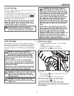
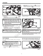
Page 16: ...ard Starting with Electric Start Figure 11 IMPORTANT To extend the life of the starter use short starting cycles five seconds maximum Wait one minute between starting cycles NOTE If the engine does no...

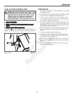
Page 17: ...in the MAINTENANCE section of this manual Rocks and gravel must not be picked up and thrown by the machine 6 After the snowthrowing job has been completed allow the engine to idle for a few minutes t...

Page 18: ...have been subjected to operator abuse or negligence To receive full value from the warranty operator must maintain snow thrower as instructed in this manual The above Service Recommendations are supp...

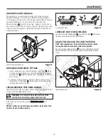
Page 19: ...rag by tightening the nut C C Figure 16 Tightening the nut will limit the chute from moving without the operator turning the chute rotation crank Chute Rotation Gear Figure 16 C A B MAINTENANCE Lubric...

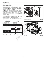
Page 20: ...k A A Figure 17 Be sure original container is marked A P I service SF or higher Do not use SAE10W40 oil as it may not provide proper lubrication See Chart for oil recommendations Drain Oil Position sn...

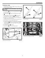
Page 21: ...sure that the primer button hose and the ignition wire are connected 7 Mount the snow hood to the engine and secure with the mounting screws 8 Connect the choke control knob A A Figure 21 with the cho...

Page 22: ...B WARNING Be certain to maintain proper ground clearance for your particular area to be cleared Objects such as gravel rocks or other debris if struck by the impeller may be thrown with sufficient for...

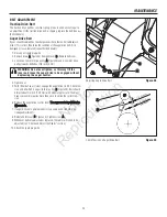
Page 23: ...use the auger drive to be engaged without depressing the auger control 4 Tighten nut 5 With the aid of an assistant engage the auger drive clutch Check ten sion on belt which is opposite idler pulley...

Page 24: ...l lever released the hook A A Figure 27 should barely touch the lever B B without raising it There can be a maximum of 1 32 0 8 mm clearance 2 To adjust loosen the nut C C by holding the adjusting fla...

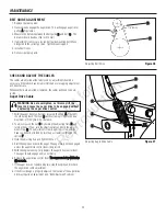
Page 25: ...able adjustment bracket Move the Z hook down to the next adjustment hole 7 Pull the traction drive cable up through the cable adjustment bracket 8 Put the cable boot over the cable adjustment bracket...

Page 26: ...r strikes an object which could cause damage to the unit the shear pin will break This protects the gear box and other parts from damage The shear pins A A Figure 31 are located on the auger shaft Rep...

Page 27: ...nspect all visible moving parts for damage breakage and wear Replace if necessary 7 Touch up all rusted or chipped paint surfaces sand lightly before painting 8 Cover the bare metal parts of the snow...

Page 28: ...authorized dealer Incorrect adjustment of traction drive cable Adjust traction drive cable Refer to Cable Adjustment in the MAINTENANCE section of this manual Worn or damaged friction disc Replace fr...

Page 29: ...o avoid misunderstanding which might occur between the customer and the Dealer listed below are some of the causes of product failure that the warranty does not cover Normal Wear Small Engine Powered...

Page 30: ...urchased The warranty on emissions related parts is as follows Any warranted part that is not scheduled for replacement as required maintenance in the owner s manual supplied is warranted for the warr...

Page 31: ...h SAE Society of Automotive Engineers code J1940 Small Engine Power Torque Rating Procedure and rating performance has been obtained and corrected in accordance with SAE J1995 Revision 2002 05 Torque...

Page 32: ...N o t f o r R e p r o d u c t i o n...

Page 33: ...Manuel n 1738019 R v B Rev Date 04 2009 Manuel d Utilisation Souffleuses neige pousser R f fab Description 1695724 Souffleuse neige double d tente 11 5 TP 27 po N o t f o r R e p r o d u c t i o n...

Page 34: ...es directives Sauvegardez ces instructions pour votre r f rence O nous trouver Vous n avez pas besoin de chercher bien loin pour trouver le support et service Briggs Stratton pour votre souf euse neig...

Page 35: ...SAGE DE LA BO TE D ENGRENAGE DE VIS SANS FIN 19 GRAISSAGE DE L ARBRE DE VIS SANS FIN 19 CONTR LER LUBRIFIER LA TRINGLERIE MAIN LIBRE 19 LUBRIFIER LE PIGNON DE ROTATION DE GOULOTTE 19 R GLER LE TIRAGE...

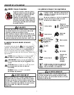
Page 36: ...de faire fonctionner la souffleuse neige Turbine rotative Maintenez la souffleuse neige une distance de s curit Tari re rotative Engrenages rotatifs Ne cherchez jamais atteindre les l ments rotatifs O...

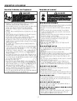
Page 37: ...angereux endommager l quipement et annuler la garantie du produit DANGER Lisez comprenez et suivez toutes les instructions sur la souffleuse neige et dans le manuel de l utilisateur avant d utiliser c...

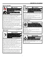
Page 38: ...t extr mement inflammables et explosifs Manipulez toujours avec extr me soin Le fait de ne pas observer ces instructions de s curit peut causer un incendie ou une explosion entra nant de graves br lur...

Page 39: ...prudence lorsque vous utilisez la souffleuse ou lui faites traverser des chemins des all es ou des routes de gravier R glez la hauteur du carter du collecteur pour d blayer les surfaces en gravier ou...

Page 40: ...nnement et des performances en toute 0 Le fait de ne pas observer les instructions de s curit de ce manuel provoquera de graves blessures voire m me la mort Entretien et remisage S il y a une fuite de...

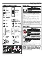
Page 41: ...XX XXXXXX IMPORTANT ENGINE INFORMATION BRIGGS STRATTON CORPORATION R f 278297 R f 277953 R f 1737869 tiquette de la commande de tari re R f 1737870 tiquette de la com mande de traction Ce symbole sign...

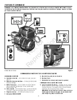
Page 42: ...du moteur emplacement du symbole COMMANDES DE LA SOUFFLEUSE NEIGE A Levier du s lecteur de vitesse Permet de choisir un rapport de vitesse parmi les six 6 en marche avant et deux 2 en marche arri re...

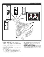
Page 43: ...ner la poign e dans le sens des aiguilles d une montre pour tourner la goulotte vers la droite Tourner la poign e dans le sens in verse pour tourner la goulotte vers la gauche Commandes de la soufleus...

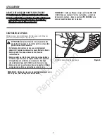
Page 44: ...e structurellement peuvent affaiblir ou d former la roue Ne pas en avant ou sur le pneu lorsqu un gonfler Utilisez un approprier outil vous permettre un stand c t REMARQUE V rifier la pression de gonf...

Page 45: ...nce d huile et autres d bris AVERTISSEMENT Ne jamais faire tourner le moteur l int rieur ou dans des endroits clos et mal ventil s Les gaz d chappement du moteur contiennent du MONOXYDE DE CARBONE un...

Page 46: ...huile et v rifier le niveau d huile REMARQUE Ne pas v rifier le niveau d huile durant la marche du moteur 5 Le cas ch ant ajouter de l huile jusqu au rep re FULL Plein sur le bouchon jauge d huile Ne...

Page 47: ...ser le d marreur lectrique Si la maison comporte un circuit lectrique trois fils avec terre mais qu aucune prise n est disponible pour brancher le d marreur lectrique faire installer une prise avec te...

Page 48: ...e du cordon de lanceur Figure 10 A D marrage lectrique Figure 11 A B ARR TER LE MOTEUR Faire tourner le moteur pendant quelques minutes pour faire vaporer toute humidit pr sente sur le moteur AVERTIS...

Page 49: ...tilisation 8 Nettoyer les d p ts de neige et tous les d bris de l ensemble de la souffleuse neige puis la rincer l eau si possible pour liminer tout le sel et autres substances chimiques Essuyer la so...

Page 50: ...es l ments ayant subi un emploi abusif ou des n gligences Pour b n ficier pleinement de la garantie veiller entretenir la souffleuse neige conform ment aux instructions de ce manuel Les Conseils d ent...

Page 51: ...nt d poser les goupilles et lubrifier les graisseurs zerk de l arbre de vis sans fin B B Faire tourner la vis sans fin plusieurs fois sur son arbre et remettre les goupilles de cisaillement en place C...

Page 52: ...A P I SF ou sup rieur Ne pas utiliser d huile SAE 10W40 car la lubrification peut tre insuffisante Voir les huiles recommand es dans le tableau ci contre Vidanger l huile Placer la souffleuse neige d...

Page 53: ...d amor age et le c ble d allumage sont branch s 7 Poser le capot neige sur le moteur et l attacher avec les vis de fixation 8 Raccorder le bouton de commande de starter A A Figure 21 l arbre de start...

Page 54: ...25 heures de marche Changer la bouge Figure 22 si les lectrodes sont piqu es ou br l es ou si la porcelaine est fissur e 1 D poser le capot neige Voir la section D POSER LE CAPOT NEIGE 2 Nettoyer la b...

Page 55: ...trop serrer car cela peut relever le levier et forcer l engagement de l entra nement de vis sans fin alors que la commande de vis sans fin n est pas actionn e 4 Serrer l crou 5 Avec l aide d un assist...

Page 56: ...er le levier B B sans le relever Il peut y avoir un espacement de 0 8 mm 1 32 pouce maximum 2 Pour ajuster desserrer l crou C C en tenant le manchon m plats D D tout en faisant tourner l crou Ensuite...

Page 57: ...errure de r glage de c ble Placer le crochet en Z dans le trou de r glage suivant 7 Tirer le c ble de commande de traction vers l arri re de la ferrure de r glage de c ble 8 Remettre la gaine de c ble...

Page 58: ...eurte un objet susceptible d endommager la machine la goupille de cisaillement se casse Ceci prot ge la bo te d engrenages et les autres pi ces de la machine Les goupilles de cisaillement A A Figure 3...

Page 59: ...l tat et du degr d usure de toutes les pi ces mobiles visibles Les changer le cas ch ant 7 Retoucher toutes les surfaces peintes rouill es ou caill es poncer l g rement avant de peindre 8 Couvrir tout...

Page 60: ...ogu R glage incorrect du c ble de commande de traction R gler le c ble de commande de traction Se reporter Contr le et r glage des c bles dans la section ENTRETIEN de ce manuel Roue de friction us e o...

Page 61: ...ible entre le client et le concessionnaire une liste de certaines causes de d faillances de produit non couvertes par la garantie figure ci dessous Usure normale Le petit mat riel motoris tel que tous...

Page 62: ...out d faut de mati re ou de construction susceptible d entra ner la d faillance d une pi ce garantie et qu il est mat riellement identique en tous points au moteur d crit dans la demande de certificat...

Page 63: ...e conform ment au code J1940 proc dure de calcul de la puissance et du couple des petits moteurs de la SAE Society of Automotive Engineers et les performances th oriques ont t obtenues et corrig es se...

Page 64: ...N o t f o r R e p r o d u c t i o n...

Reviews: