- 24 -
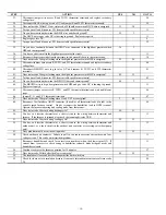
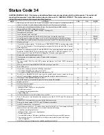
STEP ACTION YES
NO
GO
TO
40.
Remove tape from door switch, turn power off at main disconnect, and remove jumper across
R and W/W1.
41
41.
Is the blower wheel firmly mounted on motor shaft?
42
26
42.
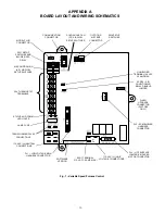
Does the model plug PL4 match the part number specified on the Model Plug Chart in the
upper left hand corner of wiring schematic?
44 43
43.
Replace model plug.
10
44.
Turn power on and depress door switch. Use a piece of tape to hold switch closed.
45
45.
Jumper R and W/W1 thermostat terminals.
46
46.
Does status code 33 occur during low heat?
47
57
47.
Clean or replace filter if necessary, then recycle furnace after limit resets.
48
48.
Observe furnace operation for 25 minutes or until status code 33 starts flashing.
49
49.
Does status code 33 occur?
50
10
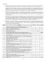
50.
Is furnace considerably overfired (10% or more)? Clock input rate. Do not use manifold
pressure method unless using propane.
51 52
51.
Ensure gas inlet pressure and burner orifices (natural or propane) are correct. Then adjust gas
valve to proper rate per Installation, Start-Up, and Operating Instructions. If it cannot be
adjusted to proper rate, replace gas valve.
10
52.
Is temperature rise within rise range?
54
53
53.
Does the installation have a bypass humidifier or zoning system bypass?
58
61
54.
Turn power off and install a temperature probe in front of limit switch button.
55
55.
Turn power on and cycle unit. Does limit switch open at a temperature at least 10 deg. F
below temperature setpoint for limit switch? (EXAMPLE: The setpoint is 220 deg F, but the
switch opens at a temperature below 210 deg F.)
18 56
56.
The problem may be related to poor air distribution or excessive pressure drop across filter.
Check filter and return-air grilles for blockage. Add turning vanes, more supply openings, or
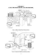
more return-air openings. Use Appendix D to evaluate external static pressure.
26
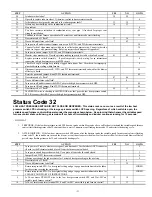
57.
While the unit is operating in low heat jumper R and W2.
47
58.
With blower access panel in place record temperature rise across return air duct before and
after the bypass.
59
59.
Is temperature rise from bypass greater than 15 deg. F?
60
61
60.
The bypass is oversized. Adjust damper or replace with properly sized bypass.
10
61.
Does installation have modulating zone dampers?
62
66
62.
Disable modulating zone damper system with all dampers in open position except bypass
damper. If installation is equipped with a bypass damper, it should be in the closed position.
63
63.
Turn power off and disconnect jumper from the R thermostat terminal. Turn power back on
and reconnect jumper to R thermostat terminal. Observe for 15 minutes with the blower access
panel in place.
64
64.
Does status code 33 flash?
66
65
65.
The problem is caused by the modulating zone damper system. Check the zoning system
manufacturer’s Installation and Troubleshooting guide for corrective action.
10
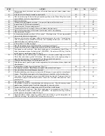
66.
Turn power off and install a temperature probe in front of limit switch button.
67
67.
Turn power on and cycle unit. Does limit switch open at a temperature at least 10 deg. F
below temperature setpoint for limit switch? (EXAMPLE: The setpoint is 220 deg F, but the
switch opens at a temperature below 210 deg F.)
18 68
68.
Adjust the blower airflow using dip switch SW1-3 and SW1-4 to get the temperature rise
within the rise range. On systems with User Interface set at the UI.
26


