background image

Installation Instructions

374RAN

MULTIPOISE OIL FURNACE

FOR INPUT CAPACITIES OF 70,000--154,000, SERIES B

NOTE

: Read the entire instruction manual before starting the

installation.

TABLE OF CONTENTS

PAGE

SAFETY CONSIDERATIONS

1

. . . . . . . . . . . . . . . . . . . . . . . . .

INTRODUCTION

3

. . . . . . . . . . . . . . . . . . . . . . . . . . . . . . . . . . .

LOCATION

3

. . . . . . . . . . . . . . . . . . . . . . . . . . . . . . . . . . . . . . . .

Step 1 — General

3

. . . . . . . . . . . . . . . . . . . . . . . . . . . . . . . . . . .

Step 2 — Location Relative to Cooling Equipment

4

. . . . . . . . .

INSTALLATION

4

. . . . . . . . . . . . . . . . . . . . . . . . . . . . . . . . . . . .

Step 1 — Air for Combustion and Ventilation

4

. . . . . . . . . . . . .

Step 2 — General

4

. . . . . . . . . . . . . . . . . . . . . . . . . . . . . . . . . . .

Step 3 — Ductwork Recommendations

5

. . . . . . . . . . . . . . . . . .

Step 4 — Venting

8

. . . . . . . . . . . . . . . . . . . . . . . . . . . . . . . . . . .

Step 5 — Factory--Built Chimneys

8

. . . . . . . . . . . . . . . . . . . . .

Step 6 — Oil Burner

9

. . . . . . . . . . . . . . . . . . . . . . . . . . . . . . . .

Step 7 — Oil Connections

9

. . . . . . . . . . . . . . . . . . . . . . . . . . . .

Step 8 — Barometric Draft Control

9

. . . . . . . . . . . . . . . . . . . . .

Step 9 — Blocked Vent Shut--Off (BVSO) For Chimney

Venting

9

. . . . . . . . . . . . . . . . . . . . . . . . . . . . . . . . . . . . . . . . . .

Step 10 — Electrical Connections

11

. . . . . . . . . . . . . . . . . . . . .

Step 11 — Horizontal or Downflow Installation

13

. . . . . . . . . .

START--UP, ADJUSTMENT, AND SAFETY CHECKOUT

13

.

Step 1 — Operational Checkout

13

. . . . . . . . . . . . . . . . . . . . . .

Step 2 — Sequence of Operation

13

. . . . . . . . . . . . . . . . . . . . . .

Step 3 — Combustion Check

15

. . . . . . . . . . . . . . . . . . . . . . . . .

Step 4 — Fan Adjustment Check

16

. . . . . . . . . . . . . . . . . . . . . .

Step 5 — Limit--Control Check

17

. . . . . . . . . . . . . . . . . . . . . . .

Step 6 — For Year--Round Air Conditioning

17

. . . . . . . . . . . . .

CARE AND MAINTENANCE

17

. . . . . . . . . . . . . . . . . . . . . . . .

Step 1 — General

17

. . . . . . . . . . . . . . . . . . . . . . . . . . . . . . . . . .

Step 2 — Oil Burner

17

. . . . . . . . . . . . . . . . . . . . . . . . . . . . . . .

Step 3 — Heat Exchanger and Flue Pipe

18

. . . . . . . . . . . . . . . .

Step 4 — Blower Removal

18

. . . . . . . . . . . . . . . . . . . . . . . . . .

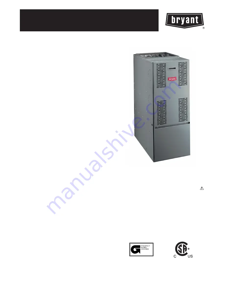
A06623

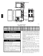
Fig. 1 -- 374RAN Multipoise Oil Furnace

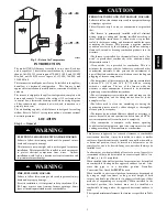
SAFETY CONSIDERATIONS

Recognize safety information. This is the safety--alert symbol

.

When you see this symbol on the furnace and in instructions or

manuals, be alert to the potential for personal injury.
Understand the signal words DANGER, WARNING, and

CAUTION. These words are used with the safety--alert symbol.

DANGER identifies the most serious hazards which

will

result in

severe personal injury or death. WARNING signifies a hazard

which

could

result in personal injury or death. CAUTION is used

to identify unsafe practices which

may

result in minor personal

injury or product and property damage. NOTE is used to highlight

suggestions which

will

result in enhanced installation, reliability, or

operation.

ama

B140.0--- B140.4--- UL727

157971

Summary of Contents for 374RAN

Page 1: ...Check 15 Step 4 Fan Adjustment Check 16 Step 5 Limit Control Check 17 Step 6 For Year Round Air Conditioning 17 CARE AND MAINTENANCE 17 Step 1 General 17 Step 2 Oil Burner 17 Step 3 Heat Exchanger an...

Page 2: ...g gasoline Never burn garbage or paper in the heating system and never leave rags paper or any flammable items around the unit WARNING All local and national code requirements governing installation o...

Page 3: ...the structure The furnace is controlled by a thermostat It may not be hot wired to provide heat continuously to the structure without thermostatic control Clean outside air is provided for combustion...

Page 4: ...st be avoided Such contamination would include the following ammonia chlorine hydrogen sulfide halogenated hydrocarbons carbon tetrachloride cleaning solvents hydrochloric acid water softening chemica...

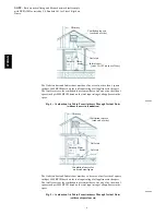
Page 5: ...side of Structure If outside air is supplied to a confined space then the 2 openings must be equal and located as above 1 If combustion air is taken through a permanent opening directly communicating...

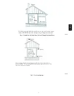
Page 6: ...each end of attic ends 1 ft 0 3m above floor Water heater A06463 Fig 4 Combustion Air Taken From Outdoors Through Vertical Ducts without louvers in foundation The Outlet air duct and Inlet air duct m...

Page 7: ...ter Outlet air duct Inlet air duct A06465 Fig 6 Combustion Air Taken From Outdoors Through Horizontal Ducts The top opening and the bottom opening must each be 8 in x 18 in when a 105 size furnace is...

Page 8: ...obstructions Any blockage must be cleared before installing furnace 3 Cleaning chimney or vent if previously used for venting a solid fuel burning appliance or fireplace 4 Confirming that all unused...

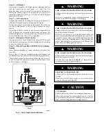
Page 9: ...installed in the flue between 2 in and 12 in from the furnace outlet and between the furnace outlet and draft regulator See Fig 9 Diagram B Riello A06403 Fig 8 Wiring Diagram for Riello Burner FIRE C...

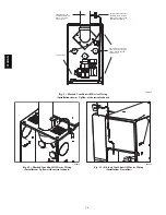
Page 10: ...e and cleaning pipes The BVSO must be installed between 2 in and 12 in from the furnace outlet Limit Switches A06614 Fig 9 Blocked Vent Shut Off Device Wiring Installation shown Upflow with vertical e...

Page 11: ...n personal injury death or property damage Do not connect aluminum wire between disconnect switch and furnace Use only copper wire WARNING The control system depends on correct polarity of power suppl...

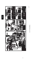
Page 12: ...12 BLOCKED VENT SHUT A06627 Fig 14 Wiring Diagram 374RAN...

Page 13: ...provided for air filter access Refer to Table 4 for filter rack flange dimensions for return air duct Table 4 Filter Size and Quantity UNIT SIZE AIR FILTER SIZE IN mm FLANGE OPENING SIZE IN mm 036105...

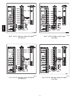
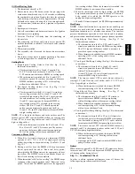
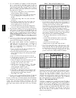
Page 14: ...ce Wiring with 1 Speed Air Conditioner A04184 Fig 16 24 VAC Oil Furnace Wiring with 2 Speed Air Conditioner A04185 Fig 17 24 VAC Oil Furnace with 1 Speed Heat Pump A04186 Fig 18 24 VAC Oil Furnace Wir...

Page 15: ...the BLWM keeps continuous blower speed until the end of Short run delay period After which the BLWM operates at the appropriate low cooling airflow When the thermostat is satisfied the BLWM switches t...

Page 16: ...ncluded with damper The draft regulator should be adjusted after furnace has been firing for at least 5 min and set between 0 025 and 0 035 in wc See Table 5 Table 5 Furnace Draft Conditions in wc FUR...

Page 17: ...ion for at least 15 minutes restrict return air supply by blocking filters or closing return registers and allow furnace to shut down on high limit The burner should shut off and main blower should co...

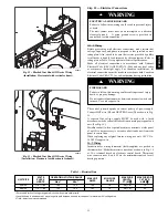
Page 18: ...required If cleaning is necessary the following steps should be performed BURN HAZARD Failure to follow this caution may result in personal injury If furnace has been in operation some surfaces may b...

Page 19: ...D13 R13 JW2 JW3 JW7 LED7 GRN R14 R12 D17 D18 D19 D21 D15 D16 LED4 LED3 LED5 LED7 LED8 LED1 GRN GRN GRN GRN GRN GRN P3 Y Y Y2 G DH O W R C HSC 1 1168 83 1 NOTES 1 The Red LED to the right of P 1 will i...

Page 20: ...SW2 COOL DIP SWITCH POSITION A C SIZE TON AIRFLOW CFM EXTERNAL STATIC PRESSURE IN WC 0 2 0 5 0 7 0 9 A 1 OFF 2 OFF 3 0 918 973 973 827 A 1 OFF 2 OFF 1010 1070 1070 910 A 1 OFF 2 OFF 826 876 876 744 B...

Page 21: ...OLING SW2 COOL DIP SWITCH POSITION A C SIZE TON AIRFLOW CFM EXTERNAL STATIC PRESSURE IN WC 0 2 0 5 0 7 0 9 A 1 OFF 2 OFF 5 0 1738 1738 1738 1725 A 1 OFF 2 OFF 1912 1912 1912 1898 A 1 OFF 2 OFF 1564 15...

Page 22: ...nge at any time specifications or designs without notice and without incurring obligations E2009 Bryant Heating Cooling Systems 7310 W Morris St Indianapolis IN 46231 Printed in U S A Edition Date 05...

Reviews: