11
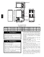
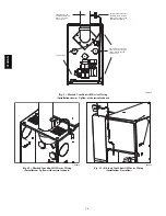
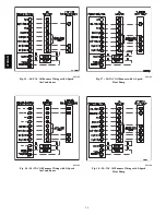
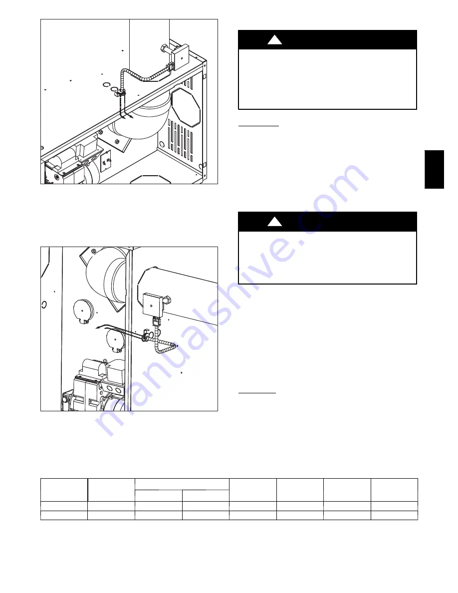
A06617
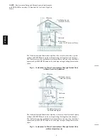
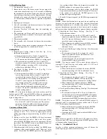
Fig. 12 -- Blocked Vent Shut--Off Device Wiring
(Installation: Horizontal with vertical exhaust)
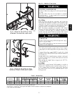
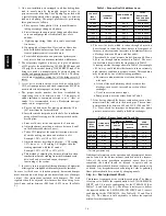
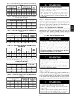
A06618
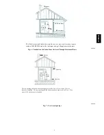
Fig. 13 -- Blocked Vent Shut--Off Device Wiring
(Installation: Horizontal with horizontal exhaust)
Step 10 — Electrical Connections
ELECTRICAL SHOCK HAZARD
Failure to follow this warning could result in personal injury
or death.
The unit cabinet must have an uninterrupted or unbroken
electrical ground.
A green ground screw is provided in
control box for this connection.
!
WARNING
115--V Wiring
Before proceeding with electrical connections, make certain that
voltage, frequency, and phase correspond to that specified on unit
rating plate. Also, check to be sure that service provided by utility
is sufficient to handle load imposed by this equipment. Refer to
rating plate or Table 3 for equipment electrical specifications.
Make all electrical connections in accordance with National
Electrical Code (NEC) ANSI/NFPA 70--2005 and any local codes
or ordinances that might apply. For Canadian installations, all
electrical connections must be made in accordance with Canadian
Electrical Code CSA C22.1 or sub--authorities having jurisdiction.
FIRE HAZARD
Failure to follow this warning could result in personal injury,
death, or property damage.
Do not connect aluminum wire between disconnect switch and
furnace. Use only copper wire.
!
WARNING
The control system depends on correct polarity of power supply.
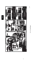
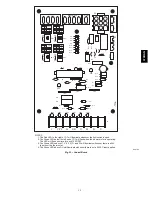
Connect HOT wire (H) and NEUTRAL wire (N) as shown in Fig.
14.
A separate line voltage supply MUST be used with a fused
disconnect switch or circuit breaker between main power panel and
unit. (See Fig. 14.)
Metallic conduit (where required/used) may terminate at side panel
of unit. It is not necessary to extend conduit inside unit from side
panel to control box.
When replacing any original furnace wiring, use only 105
_
C No.
14 AWG copper wire.
24--V Wiring
Instructions for wiring thermostat (field--supplied) are packed in
thermostat box. Make thermostat connections as shown in Fig. 14
at 24--v terminal board on electronic control board. Thermostat
wire connections at R and W are the minimum required for oil
heating operation.
Table 3 – Electrical Data
UNIT SIZE
VOLTS
PHASE
HERTZ
OPERATING VOLTAGE RANGE
MAX UNIT
AMPS
MIN. WIRE
GAUGE
MAX WIRE
LENGTH
FT. (M)
{
MAX FUSE OR
CKT BKR
AMPS
}
Max.*
Min.*
036105
115---1---60
132
104
12.2
14
26 (7.9)
15
060120
115---1---60
132
104
15.7
12
26 (7.9)
20
* Permissible limits of voltage range at which unit will operate satisfactorily.
{
Length shown is as measured 1 way along wire path between unit and service panel for maximum 2% voltage drop.
}
Time---delay fuse is recommended
374RAN


