background image

548J

SINGLE PACKAGE HEAT PUMP/ELECTRIC HEAT

NOMINAL 3 TO 8.5 TONS

WITH PURON

R

(R--410A) REFRIGERANT

Service and Maintenance Instructions

TABLE OF CONTENTS

SAFETY CONSIDERATIONS

1

. . . . . . . . . . . . . . . . . . . .

UNIT ARRANGEMENT AND ACCESS

3

. . . . . . . . . . .

SUPPLY FAN (BLOWER) SECTION

4

. . . . . . . . . . . . . .

HEAT PUMP REFRIGERATION SYSTEM

8

. . . . . . . . .

PURON

R

(R--410A) REFRIGERANT

13

. . . . . . . . . . . . .

COOLING CHARGING CHARTS

14

. . . . . . . . . . . . . . . .

CONVENIENCE OUTLETS

19

. . . . . . . . . . . . . . . . . . . .

HEAT PUMP CONTROLS

20

. . . . . . . . . . . . . . . . . . . . . .

PROTECTIVE CONTROLS

20

. . . . . . . . . . . . . . . . . . . . .

COMMERCIAL DEFROST CONTROL

21

. . . . . . . . . . .

ELECTRIC HEATERS

24

. . . . . . . . . . . . . . . . . . . . . . . . .

SMOKE DETECTORS

26

. . . . . . . . . . . . . . . . . . . . . . . . .

RTU--MP CONTROL SYSTEM

33

. . . . . . . . . . . . . . . . . .

ECONOMIZER SYSTEMS

47

. . . . . . . . . . . . . . . . . . . . .

WIRING DIAGRAMS

56

. . . . . . . . . . . . . . . . . . . . . . . . .

PRE--START-UP

58

. . . . . . . . . . . . . . . . . . . . . . . . . . . . . .

START-UP, GENERAL

58

. . . . . . . . . . . . . . . . . . . . . . . . .

START-UP, RTU--MP CONTROL

59

. . . . . . . . . . . . . . . .

OPERATING SEQUENCE

62

. . . . . . . . . . . . . . . . . . . . . .

FASTENER TORQUE VALUES

67

. . . . . . . . . . . . . . . . .

APPENDIX I. MODEL NUMBER SIGNIFICANCE

68

. . .

APPENDIX II. PHYSICAL DATA

69

. . . . . . . . . . . . . . . .

APPENDIX III. FAN PERFORMANCE

71

. . . . . . . . . . .

APPENDIX IV. ELECTRICAL INFORMATION

82

. . . .

APPENDIX V. WIRING DIAGRAM LIST

96

. . . . . . . . .

APPENDIX VI. MOTORMASTER SENSOR

LOCATIONS

97

. . . . . . . . . . . . . . . . . . . . . . . . . . . . . . . . .

UNIT START-UP CHECKLIST

99

. . . . . . . . . . . . . . . . . .

SAFETY CONSIDERATIONS

Installation and servicing of air-conditioning equipment

can be hazardous due to system pressure and electrical

components. Only trained and qualified service personnel

should install, repair, or service air-conditioning

equipment. Untrained personnel can perform the basic

maintenance functions of replacing filters. Trained service

personnel should perform all other operations.

When working on air-conditioning equipment, observe

precautions in the literature, tags and labels attached to

the unit, and other safety precautions that may apply.

Follow all safety codes. Wear safety glasses and work

gloves. Use quenching cloth for unbrazing operations.

Have fire extinguishers available for all brazing

operations.

Follow all safety codes. Wear safety glasses and work

gloves. Use quenching cloth for brazing operations. Have

fire extinguisher available. Read these instructions

thoroughly and follow all warnings or cautions attached to

the unit. Consult local building codes and National

Electrical Code (NEC) for special requirements.

Recognize safety information. This is the safety--alert

symbol

. When you see this symbol on the unit and in

instructions or manuals, be alert to the potential for

personal injury.

Understand the signal words DANGER, WARNING, and

CAUTION. These words are used with the safety--alert

symbol. DANGER identifies the most serious hazards

which

will

result in severe personal injury or death.

WARNING signifies a hazard which

could

result in

personal injury or death. CAUTION is used to identify

unsafe practices which

may

result in minor personal

injury or product and property damage. NOTE is used to

highlight suggestions which

will

result in enhanced

installation, reliability, or operation.

Summary of Contents for 548J

Page 1: ...f replacing filters Trained service personnel should perform all other operations When working on air conditioning equipment observe precautions in the literature tags and labels attached to the unit and other safety precautions that may apply Follow all safety codes Wear safety glasses and work gloves Use quenching cloth for unbrazing operations Have fire extinguishers available for all brazing o...

Page 2: ...low this warning could cause personal injury death and or equipment damage Puron R 410A refrigerant systems operate at higher pressures than standard R 22 systems Do not use R 22 service equipment or components on Puron refrigerant equipment WARNING PERSONAL INJURY AND ENVIRONMENTAL HAZARD Failure to follow this warning could cause personal injury or death Relieve pressure and recover all refriger...

Page 3: ... Indoor coil cleaning S Supply blower motor amperage Electric Heating S Power wire connections S Fuses ready S Manual reset limit switch is closed Economizer or Outside Air Damper S Inlet filters condition S Check damper travel economizer S Check gear and dampers for debris and dirt Air Filters and Screens Each unit is equipped with return air filters If the unit has an economizer it will also hav...

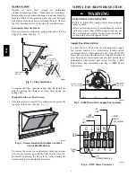
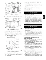
Page 4: ...the retainer up until the filter can be removed Re install by placing the frame in its track rotating the retainer back down and tighten all screws SUPPLY FAN BLOWER SECTION ELECTRICAL SHOCK HAZARD Failure to follow this warning could cause personal injury or death Before performing service or maintenance operations on the fan system shut off all unit power and tag out the unit disconnect switch D...

Page 5: ...specific speed value assigned to each control tap setting At the Position 5 tap the motor speed is approximately 1050 RPM 17 5 r s but it will vary depending on fan wheel loading Selecting speed tap The five communications terminals are each programmed to provide a different motor torque output See Table 1 Factory default tap selection is Position 1 for lowest torque speed operation Table 1 548J S...

Page 6: ...driver pulley is on the motor The pulleys are connected using a V type belt See Fig 8 C07087 Fig 8 Belt Drive Motor Mounting Belt Check the belt condition and tension quarterly Inspect the belt for signs of cracking fraying or glazing along the inside surfaces Check belt tension by using a spring force tool such as Browning s Part Number Belt Tension Checker or equivalent tool tension should be 6 ...

Page 7: ...fications 4 Recheck belt tension Bearings This fan system uses bearings featuring concentric split locking collars The collars are tightened through a cap screw bridging the split portion of the collar The cap screw has a Torx T25 socket head To tighten the locking collar Hold the locking collar tightly against the inner race of the bearing and torque the cap screw to 65 70 in lb 7 4 7 9 Nm See Fi...

Page 8: ...ded coil will drive the fibers and dirt into the coil This will make cleaning efforts more difficult Surface loaded fibers must be completely removed prior to using low velocity clean water rinse Periodic Clean Water Rinse A periodic clean water rinse is very beneficial for coils that are applied in coastal or industrial environments However it is very important that the water rinse is made with v...

Page 9: ...ry difficult to rinse out of the coil and can accelerate corrosion at the fin tube interface where dissimilar materials are in contact If there is dirt below the surface of the coil use the Totaline environmentally sound coil cleaner as described above CAUTION UNIT DAMAGE HAZARD Failure to follow this caution may result in reduced unit performance High velocity water from a pressure washer garden ...

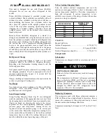
Page 10: ...or reversing valve dual function outdoor coil with vapor header check valve cooling liquid line with filter drier and check valve dual function indoor coil with vapor header check valve and heating liquid line with check valve and strainer Unit sizes 04A 07A have a single compressor circuit unit sizes 08D and 09D have two compressor circuits See Fig 14 for typical unit piping schematic unit size 0...

Page 11: ...lve and exit through the remaining tube on the vapor header In this last pass through the coil the refrigerant is subcooled Subcooled liquid exits at the last Acutrol tee see Fig 18 where the side port is connected to the specific mode liquid line From Condenser Coil Circuits To Transfer Header C09230 Fig 16 Heat Pump Acutrol Flow as Condenser Function Exiting First Pass To Condensing Circuit From...

Page 12: ... coil disconnect the outdoor fan motor Start the circuit in a Heating Mode jumper R to W1 or W2 and observe the frost pattern on the face of the outdoor coil Failure to develop frost at an outlet tube can indicate a plugged or a missing orifice Refrigerant System Pressure Access Ports There are two access ports in each circuit on the suction tube near the compressor and on the discharge tube near ...

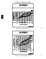
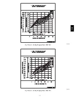
Page 13: ... Cooling Using Cooling Charging Charts Fig 20 vary refrigerant until the conditions of the appropriate chart are met Note the charging charts are different from type normally used Charts are based on charging the units to the correct superheat for the various operating conditions Accurate pressure gauge and temperature sensing device are required Connect the pressure gauge to the service port on t...

Page 14: ...14 COOLING CHARGING CHARTS C09184 Fig 20 Cooling Charging Charts 548J 04A C09185 Fig 20 cont Cooling Charging Charts 548J 05A 548J ...

Page 15: ...15 C09186 Fig 20 cont Cooling Charging Charts 548J 06A C09187 Fig 20 cont Cooling Charging Charts 548J 07A 548J ...

Page 16: ...16 C09188 Fig 20 cont Cooling Charging Charts 548J 08D C09189 Fig 20 cont Cooling Charging Charts 548J 09D 548J ...

Page 17: ... compressor The suction and discharge pressure levels should now move to their normal start up levels NOTE When the compressor is rotating in the wrong direction the unit makes an elevated level of noise and does not provide cooling Filter Drier Replace whenever refrigerant system is exposed to atmosphere Only use factory specified liquid line filter driers with working pressures no less than 650 ...

Page 18: ... indoor fan heating motor or capacitor Replace Restriction in refrigerant system Locate restriction and remove Compressor Operates Continuously Dirty air filter Replace filter Unit undersized for load Decrease load or increase unit size Thermostat set too low cooling Reset thermostat Low refrigerant charge Locate leak repair and recharge Air in system Recover refrigerant evacuate system and rechar...

Page 19: ...ing and latching RECEPTACLE NOT INCLUDED COVER WHILE IN USE WEATHERPROOF BASE PLATE FOR GFCI RECEPTACLE C09022 Fig 23 Weatherproof Cover Installation Non powered type This type requires the field installation of a general purpose 125 volt 15 A circuit powered from a source elsewhere in the building Observe national and local codes when selecting wire size fuse or breaker requirements and disconnec...

Page 20: ...nfirmed Observe National Electrical Code Article 210 Branch Circuits for use of convenience outlets HEAT PUMP CONTROLS Controls Terminal Board The Controls Terminal Board CTB is a large printed circuit board that is located in the center of the unit control box This printed circuit board contains multiple termination strips and connectors to simplify factory control box wiring and field control co...

Page 21: ...ine the cause and correct it The External motor overload device is a specially calibrated circuit breaker that is UL recognized as a motor overload controller It is an overcurrent device When the motor current exceeds the circuit breaker setpoint the device opens all motor power leads and the motor shuts down Reset requires a manual reset at the overload switch This device designated IFCB is locat...

Page 22: ... I O Connection Pin Number Unit Connection Note Speed Up Jumper JMP17 Speed Up Jumper JMP18 Jumper for 1 3 secs Factory Test defrost runs for 9 secs Jumper for 5 20 secs Forced Defrost defrost runs for 30 secs if DFT2 is open Reversing valve control The DFB has two outputs for unit reversing valve control Operation of the reversing valves is based on internal logic this application does not use an...

Page 23: ...ever comes first On sizes 08 09 Circuit 1 s defrost thermostat DFT1 located on the upper circuit of the outdoor coil cannot initiate a unit defrost cycle only DFT2 may do this But once Circuit 2 is in defrost the DFB will monitor the status of DFT1 If DFT1 closes during a Circuit 2 defrost cycle Circuit 1 will also enter a defrost cycle Circuit 1 s defrost cycle will end when DFT1 opens indicating...

Page 24: ...e compartment on tracks along the bottom of the heater opening See Fig 29 Fig 30 and Fig 31 Not all available heater modules may be used in every unit Use only those heater modules that are UL listed for use in a specific size unit Refer to the label on the unit cabinet re approved heaters Unit heaters are marked with Heater Model Numbers But heaters are ordered as and shipped in cartons marked wi...

Page 25: ...itches and a pilot circuit manual reset limit switch to protect the unit against over temperature situations Line break auto reset limit switches are mounted on the base plate of each heater module See Fig 33 These are accessed through the indoor access panel Remove the switch by removing two screws into the base plate and extracting the existing switch Pilot circuit manual reset limit switch is l...

Page 26: ...er Assembly Sensor The sensor see Fig 36 includes a plastic housing a printed circuit board a clear plastic cover a sampling tube inlet and an exhaust tube The sampling tube when used and exhaust tube are attached during installation The sampling tube varies in length depending on the size of the rooftop unit The clear plastic cover permits visual inspections without having to disassemble the sens...

Page 27: ...le Return Air Detector module shipping position shown RA detector must be moved from shipping position to operating position by installer C07307 Fig 38 Typical Return Air Detector Location Return Air with Economizer The sampling tube is inserted through the side plates of the economizer housing placing it across the return air opening on the unit basepan See Fig 39 The holes in the sampling tube f...

Page 28: ...is removed at Smoke Detector input on CTB Control Terminal Board all unit operations cease immediately Highlight D On smoke alarm condition the smoke detector NO Alarm contact will close supplying 24 v power to GRA conductor Highlight E GRA lead at Smoke Alarm input on CTB provides 24 v signal to FIOP DDC control RTU MP The 24 v signal is conveyed to RTU MP s J1 10 input terminal This signal initi...

Page 29: ...r seven seconds 2 Verify that the controller s Alarm LED turns on 3 Reset the sensor by pressing the test reset switch for two seconds 4 Verify that the controller s Alarm LED turns off Dirty Controller Test The dirty controller test checks the controller s ability to initiate a dirty sensor test and indicate its results OPERATIONAL TEST HAZARD Failure to follow this caution may result in personne...

Page 30: ...er before performing the test If the duct detector is connected to a fire alarm system notify the proper authorities before performing the test CAUTION CRSDTEST001A00 Remote Alarm Test Procedure 1 Turn the key switch to the RESET TEST position for seven seconds 2 Verify that the test reset station s Alarm LED turns on 3 Reset the sensor by turning the key switch to the RESET TEST position for two ...

Page 31: ...t detector then perform a sensor alarm test Airflow HVAC duct Sampling tube Retainer clip Optic plate Optic housing Sensor housing C07305 Fig 44 Sensor Cleaning Diagram Indicators Normal State The smoke detector operates in the normal state in the absence of any trouble conditions and when its sensing chamber is free of smoke In the normal state the Power LED on both the sensor and the controller ...

Page 32: ...required Controller s Trouble LED is Flashing 1 One or both of the sensors is 100 dirty 2 Determine which Dirty LED is flashing then clean that sensor assembly as described in the detector cleaning section Sensor s Trouble LED is On 1 Check the sensor s Dirty LED If it is flashing the sensor is dirty and must be cleaned 2 Check the sensor s cover If it is loose or missing se cure the cover to the ...

Page 33: ...Virtual BACview loaded on a portable PC must be used with the RTU MP controller Connection to the RTU MP board is at the J12 access port see Fig 46 The RTU MP control is factory mounted in the 548J unit s main control box to the left of the CTB See Fig 47 or Fig 48 Factory wiring is completed through harnesses connected to the CTB Field connections for RTU MP sensors will be made at the Phoenix co...

Page 34: ...34 C099015 Fig 47 RTU MP System Control Wiring Diagram 548J 04A 548J 07A Units 548J ...

Page 35: ...35 C099025 Fig 48 RTU MP System Control Wiring Diagram 548J 08D 548J 09D Units 548J ...

Page 36: ...Relay State aux_2 DO Relay 24VAC 1A J11 3 Dehumidification Relay State humizer DO Relay 24VAC 1A J11 7 8 LEGEND AI Analog Input AO Analog Output DI Discrete Input DO Discrete Output These inputs if installed take the place of the default input on the specific channel according to schematic Parallel pins J5 1 J2 6 J5 3 J1 10 J5 5 J1 2 are used for field installation Refer to the input configuration...

Page 37: ...e the RTU MP at plugs J1 J2 J4 J5 J11 and J20 All field control wiring that connects to the RTU MP must be routed through the raceway built into the corner post as shown in Fig 50 The raceway provides the UL required clearance between high and low voltage wiring Pass the control wires through the hole provided in the corner post then feed the wires thorough the raceway to the RTU MP Connect to the...

Page 38: ...THSW The enthalpy control 33CSENTHSW is available as a field installed accessory to be used with the EconoMi er2 damper system The outdoor air enthalpy sensor is part of the enthalpy control The separate field installed accessory return air enthalpy sensor 33CSENTSEN is required for differential enthalpy control See Return Air Enthalpy Sensor for details Locate the enthalpy control in the economiz...

Page 39: ...a range of 0 to 2000 ppm and a linear mA output of 4 to 20 Refer to the instructions supplied with the CO2 sensor for electrical requirements and terminal locations See Fig 58 for typical CO2 sensor wiring schematic 8 7 6 5 4 3 2 1 2 1 H G 24 VAC OR 24 VDC NC ALARM RELAY CONTACTS COM NO 0 10VDC SIG COM J4 6 4 20mA J4 5 C07134 Fig 58 Indoor Outdoor Air Quality CO2 Sensor 33ZCSENCO2 Typical Wiring D...

Page 40: ...ssory is a field installed accessory This accessory detects plugged filters When installing this accessory the unit must be configured for filter status by setting MENU Config Inputs input 3 5 8 or 9 to Filter Status and normally open N O or normally closed N C Input 8 or 9 is recommended for easy of installation Refer to Fig 46 Fig 47 and Fig 48 for wire terminations at J5 Fan Status The fan stat...

Page 41: ...nWorks Option Card LON OC was designed to connect to the RTU MP This accessory card is needed for LonWorks and has to be ordered and connected using the ribbon cable to plug J15 The RTU MP s baud rate must be set to 38 4k to communicate with the LON OC The address switches SW1 SW2 are not used with LonWorks Local Access BACview6 Handheld The BACview6 is a keypad display interface used to connect t...

Page 42: ...hows And Error LED shows Status is 2 flashes per second Off Normal 2 flashes per second 2 flashes alternating with Run LED Five minute auto restart delay after system error 2 flashes per second 3 flashes then off Control module has just been formatted 2 flashes per second 4 flashes then pause Two or more devices on this network have the same ARC156 network address 2 flashes per second On Exec halt...

Page 43: ...figured with or without switch Dirty Filter supply fan run time exceeded filter switch configuration wrong Switch Configuration Alarm sw_cfg_alarm Alarm Generated Disable misconfigured switch functions Configure correctly More than one binary input is configured for the same purpose More then one discrete input is configured to provide the same function Misconfigured Analog Input an_cfg_alarm Alar...

Page 44: ...afety and humidistat would function normally and Fan Status inputs 5 8 will be interpreted as No Function Misconfigured Analog Input This occurs if more than one analog input inputs 1 2 is configured for the same sensor When this happens the two inputs will be disabled as inputs This alarm will automatically be cleared when configuration is corrected An example of this would be Input 1 IAQ Sensor ...

Page 45: ...mprised of both Master and Slave nodes Valid MAC addresses for Master nodes are 0 127 and valid addresses for Slave nodes are 0 254 NOTE See RTU MP 3rd Party Integration Guide for Protocol Maps Device Instance 0160001 1 PRGs loaded 1 PRGs running Module status Firmware sections validated in flash memory Boot16 H v2 06 001 Jun 19 2007 RTU MP DRIVER v2 09 050 Jun 26 2007 Reset counters 11 Power fail...

Page 46: ... Controller CODE NAME MEANING 01 Illegal Function The Modbus function code used in the query is not supported by the controller 02 Illegal Data Address The register address used in the query is not supported by the controller 04 Slave Device Failure The Modbus Master has attempted to write to a non existent register or a read only register in the controller Modbus 1 Verify that the BAS and control...

Page 47: ... controller s N2 slave address is set by its rotary address switches 6 Verify proper wiring between the BAS and the controller 7 Verify that the BAS is reading or writing to the proper network point addresses on the controller Download the latest points list for the controller to verify 8 Verify that the BAS is sending his requests to the proper slave address of our controller NOTE See RTU MP 3rd ...

Page 48: ...4 20mA SIGNAL OAT SENSOR 4 20 mA TO J9 ON PremierLink BOARD 24 VAC TRANSFORMER GROUND NOTES 1 Switch on actuator must be in run position for economizer to operate 2 PremierLink control requires that the standard 50HJ540569 outside air sensor be replaced by either the CROASENR001A00 dry bulb sen sor or HH57A077 enthalpy sensor 3 50HJ540573 actuator consists of the 50HJ540567 actuator and a harness ...

Page 49: ...ply air sensor signals between minimum position and either maximum position DCV or fully open supply air signal Modulation is based on the greater of DCV and supply air sensor signals between closed and either maximum position DCV or fully open supply air signal C06053 Fig 70 EconoMi er IV Functional View EconoMi er IV Table 21 provides a summary of EconoMi er IV Troubleshooting instructions are e...

Page 50: ... using a Wall Mounted CO2 Sensor 33ZCSENCO2 CO2 for DCV Control using a Duct Mounted CO2 Sensor 33ZCSENCO2 and 33ZCASPCO2 O R CRCBDIOX005A00 CRENTDIF004A00 and CRTEMPSN002A00 accessories are used on many different base units As such these kits may contain parts that will not be needed for installation 33ZCSENCO2 is an accessory CO2 sensor 33ZCASPCO2 is an accessory aspirator box required for duct ...

Page 51: ...ts are A B C and D See Fig 76 The factory installed 620 ohm jumper must be in place across terminals SR and SR on the EconoMi er IV controller see Fig 68 In this mode of operation the outdoor air temperature is compared to the return air temperature and the lower temperature airstream is used for cooling When using this mode of changeover control turn the enthalpy setpoint potentiometer fully cloc...

Page 52: ... Settings If a separate field supplied transformer is used to power the IAQ sensor the sensor must not be grounded or the EconoMi er IV control board will be damaged When using demand ventilation the minimum damper position represents the minimum ventilation position for VOC volatile organic compounds ventilation requirements The maximum demand ventilation position is used for fully occupied venti...

Page 53: ... are open removing the 24 v signal from terminal N the EconoMi er IV will be in unoccupied mode Demand Control Ventilation DCV When using the EconoMi er IV for demand controlled ventilation there are some equipment selection criteria which should be considered When selecting the heat capacity and cool capacity of the equipment the maximum ventilation rate must be evaluated for design conditions Th...

Page 54: ...ized Follow the steps below to change the non standard settings 1 Press Clear and Mode buttons Hold at least 5 seconds until the sensor enters the Edit mode 2 Press Mode twice The STDSET Menu will appear 3 Use the Up Down button to toggle to the NONSTD menu and press Enter 4 Use the Up Down button to toggle through each of the nine variables starting with Altitude until the desired setting is reac...

Page 55: ...rformed 2 Ensure terminals AQ and AQ1 are open The LED for both DCV and Exhaust should be off The actuator should be fully closed 3 Connect a 9 v battery to AQ positive node and AQ1 negative node The LED for both DCV and Exhaust should turn on The actuator should drive to between 90 and 95 open 4 Turn the Exhaust potentiometer CW until the Exhaust LED turns off The LED should turn off when the pot...

Page 56: ... Set minimum position DCV setpoint and exhaust potentiometers to previous settings 5 Remove 620 ohm resistor from terminals SR and 6 Remove 1 2 kilo ohm checkout resistor from terminals SO and If used reconnect sensor from terminals SO and 7 Remove jumper from TR to N 8 Remove jumper from TR to 1 9 Remove 5 6 kilo ohm resistor from T and T1 Reconnect wires at T and T1 10 Remove jumper from P to P1...

Page 57: ...57 C09200 Fig 80 50TCQ Typical Unit Wiring Diagram Control D08 208 230 3 60 548J ...

Page 58: ...PERSONAL INJURY AND ENVIRONMENTAL HAZARD Failure to follow this warning could result in personal injury or death Relieve pressure and recover all refrigerant before system repair or final unit disposal Wear safety glasses and gloves when handling refrigerants Keep torches and other ignition sources away from refrigerants and oils WARNING 3 Make the following inspections a Inspect for shipping and ...

Page 59: ...rmostat energizes electric heaters if installed Check heating effects at air supply grille s If electric heaters do not energize reset limit switch located on supply fan scroll by pressing button located between terminals on the switch To shut off unit set system selector switch at OFF position Resetting thermostat at a position below room temperature temporarily shuts unit off until space tempera...

Page 60: ...on this point is exceeded the corresponding alarm will be generated and must be manually cleared on the alarm reset screen after the maintenance has been completed The timer will then begin counting its runtime again for the next maintenance interval Factory Default 0 hr NOTE Setting this configuration timer to 0 disables the alarm Compressor2 Service Hours This refers to the timer set for the Com...

Page 61: ...d to be either Normally Open N O or Normally Closed N C Input 9 is factory and field wired to pin J5 7 Do not connect inputs to both locations one function per input Factory Default Humidistat and N O Space Sensor Type This tells the controller what type of space sensor is installed to run the unit The three types that can be used are the T55 space sensor the T56 space sensor or the RS space senso...

Page 62: ...en is only accessible with the Administrator Password 1111 The ADMIN password will always override the user password OPERATING SEQUENCE Indoor Supply Fan Continuous fan operation is selected at the thermostat Terminal G is energized Defrost Board DFB receives this signal at P2 3 and it issues an output at P3 9 04A 06A Standard Static Drive option 24 v signal at P3 9 is applied to direct drive moto...

Page 63: ...ed and IFM operations cease unless Continuous Fan operation has been selected Reversing valve solenoids remain de energized until the next call for Cooling mode is initiated Cooling Unit With EconoMi er IV For Occupied mode operation of EconoMi er IV there must be a 24 v signal at terminal N provided through harness plug PL6 3 from the unit s IFC coil Removing the signal at N places the EconoMi er...

Page 64: ...tric heaters only no compression heating is energized Emergency Heat is initiated when the defrost board receives an input signal at W2 P2 6 but there is no input signal at W1 P2 7 This signal combination can be provided by thermostat configuration manual external switch selection or by servicer disconnecting the W1 field connection Upon initiation of the Emergency Heat sequence the DFB will issue...

Page 65: ...ily schedule and identify a specific day and month of the year to start and stop the unit and change control to the unoccupied heating and cooling setpoints Follow the same steps to turn on one of the twelve Holiday schedules and start and stop times Next select one out of the twelve months and one out of the thirty one days of that month The RTU MP will now ignore the Daily schedule for the speci...

Page 66: ...economizer lockout configuration default 75 S OAT SPT If any of the mentioned conditions are not true the economizer will be set to its configured minimum position The minimum damper position can be overridden by the IAQ routine described later in this section If the above conditions are true the Economizer Control Master Loop will calculate a damper position value based on the following calculati...

Page 67: ... maximum damper position configuration then it will be clamped to the configured value Demand Limit If the RTU MP receives a level 1 one degree offset 2 two degree offset or a 3 4 degree offset to the BACnet demand limit variable the controller will expand the heating and cooling setpoints by the configured demand limit setpoint value and remain in effect until the BACnet demand limit variable rec...

Page 68: ...rized 2 pos damper Heat Level Field installed electric heaters available Indoor Fan Options 000 No Heat 0 Electric Drive X13 Motor 04 06 1 Standard static option Belt Drive Coil Options Outdoor Indoor 2 Medium static option Belt Drive A Al Cu Al Cu 3 High static option Belt Drive B Precoat Al Cu Al Cu C E coat Al Cu Al Cu D E coat Al Cu E coat Al Cu E Cu Cu Al Cu F Cu Cu Cu Cu M Al Cu Al Cu Louver...

Page 69: ...78 1192 Motor Frame Size 48 48 48 56 Fan Qty Type 1 Centrifugal 1 Centrifugal 1 Centrifugal Fan Diameter in 10 x 10 10 x 10 11 x 10 10 x 10 Medium Static 3 phase Motor Qty Drive Type 1 Belt 1 Belt 1 Belt 1 Belt Max BHP 1 5 1 5 2 0 2 9 RPM Range 819 1251 920 1303 1066 1380 1066 1380 Motor Frame Size 56 56 56 56 Fan Qty Type 1 Centrifugal 1 Centrifugal 1 Centrifugal 1 Centrifugal Fan Diameter in 10 ...

Page 70: ...pe 1 Centrifugal 1 Centrifugal Fan Diameter in 15 x 15 15 x 15 Medium Static 3 phase Motor Qty Drive Type 1 Belt 1 Belt Max BHP 2 9 2 9 RPM Range 591 838 591 838 Motor Frame Size 56 56 Fan Qty Type 1 Centrifugal 1 Centrifugal Fan Diameter in 15 x 15 15 x 15 High Static 3 phase Motor Qty Drive Type 1 Belt 1 Belt Max BHP 2 9 2 9 RPM Range 838 1084 838 1084 Motor Frame Size 56 56 Fan Qty Type 1 Centr...

Page 71: ...s or accessories 3 Tabular data accounts for pressure loss due to clean filters unit casing and wet coils Factory options and accessories may add static pressure losses 4 The Fan Performance tables offer motor drive recommendations In cases when two motor drive combinations would work Bryant recommended the lower horsepower option 5 For information on the electrical properties of Bryant s motors p...

Page 72: ... 5 900 1 18 0 52 975 1 14 0 54 1050 1 10 0 56 1125 1 06 0 58 1200 1 02 0 60 1275 0 98 0 63 1350 0 94 0 65 1425 0 90 0 68 1500 0 87 0 71 Table 26 548J 04A ELECTRIC DRIVE X13 MOTOR 3 TON VERTICAL SUPPLY SPEED TORQUE TAP CFM ESP BHP 1 900 0 44 0 22 975 0 35 0 21 1050 0 24 0 20 1125 0 15 0 19 1200 0 08 0 19 1275 0 02 0 18 1350 1425 1500 2 900 0 64 0 30 975 0 53 0 29 1050 0 42 0 28 1125 0 32 0 27 1200 ...

Page 73: ... 5 1200 1 02 0 60 1300 0 97 0 64 1400 0 92 0 67 1500 0 87 0 71 1600 0 82 0 75 1700 0 77 0 79 1800 0 71 0 84 1900 0 65 0 88 2000 0 58 0 92 Table 28 548J 05A ELECTRIC DRIVE X13 MOTOR 4 TON VERTICAL SUPPLY SPEED TORQUE TAP CFM ESP BHP 1 1200 0 50 0 39 1300 0 36 0 37 1400 0 19 0 35 1500 0 10 0 33 1600 0 02 0 32 1700 1800 1900 2000 2 1200 0 80 0 55 1300 0 69 0 55 1400 0 50 0 54 1500 0 38 0 52 1600 0 24...

Page 74: ... 5 1500 1 49 0 90 1625 1 38 0 95 1750 1 28 1 00 1875 1 18 1 05 2000 1 11 1 09 2125 0 97 1 11 2250 0 72 1 07 2375 0 47 1 02 2500 0 20 0 96 Table 30 548J 06A ELECTRIC DRIVE X13 MOTOR 4 TON VERTICAL SUPPLY SPEED TORQUE TAP CFM ESP BHP 1 1500 1 00 0 70 1625 0 72 0 65 1750 0 46 0 60 1875 0 28 0 55 2000 0 14 0 51 2125 0 00 0 52 2250 2375 2500 2 1500 1 18 0 88 1625 1 00 0 90 1750 0 75 0 87 1875 0 51 0 83...

Page 75: ...2 1461 1 93 Med static High static Table 32 548J 04A 3 TON VERTICAL SUPPLY CFM AVAILABLE EXTERNAL STATIC PRESSURE IN WG 0 2 0 4 0 6 0 8 1 0 RPM BHP RPM BHP RPM BHP RPM BHP RPM BHP 900 594 0 15 740 0 25 867 0 37 981 0 52 1084 0 68 975 618 0 17 758 0 28 881 0 40 991 0 55 1092 0 71 1050 642 0 19 777 0 30 896 0 43 1003 0 58 1102 0 75 1125 668 0 22 797 0 34 912 0 47 1017 0 62 1113 0 79 1200 695 0 25 81...

Page 76: ...Face indicates field supplied drive 1 Recommend using field supplied fan pulley part no KR11AD561 motor pulley part no KR11HY181 and belt part no KR29AF041 Table 34 548J 05A 4 TON VERTICAL SUPPLY CFM AVAILABLE EXTERNAL STATIC PRESSURE IN WG 0 2 0 4 0 6 0 8 1 0 RPM BHP RPM BHP RPM BHP RPM BHP RPM BHP 1200 695 0 25 818 0 37 930 0 51 1032 0 66 1126 0 83 1300 731 0 30 849 0 43 955 0 57 1053 0 72 1145 ...

Page 77: ...75 1393 2 05 1453 2 27 1511 2 49 1566 2 72 1618 2 95 2500 1427 2 24 1487 2 47 1543 2 70 1597 2 94 1649 3 18 Med static High static Table 36 548J 06A 5 TON VERTICAL SUPPLY CFM AVAILABLE EXTERNAL STATIC PRESSURE IN WG 0 2 0 4 0 6 0 8 1 0 RPM BHP RPM BHP RPM BHP RPM BHP RPM BHP 1500 794 0 41 902 0 55 993 0 69 1074 0 85 1147 1 00 1625 840 0 49 945 0 64 1034 0 80 1113 0 96 1185 1 13 1750 888 0 59 988 0...

Page 78: ...0 3 03 1662 3 27 2700 1483 2 59 1541 2 83 1597 3 07 1650 3 32 2850 1527 2 87 1583 3 12 1638 3 37 3000 1571 3 18 1626 3 44 1680 3 70 Std static Med static High static Table 38 548J 07A 6 TON VERTICAL SUPPLY CFM AVAILABLE EXTERNAL STATIC PRESSURE IN WG 0 2 0 4 0 6 0 8 1 0 RPM BHP RPM BHP RPM BHP RPM BHP RPM BHP 1800 907 0 63 1006 0 80 1092 0 97 1169 1 14 1239 1 32 1950 965 0 77 1060 0 95 1143 1 13 1...

Page 79: ... 1 98 954 2 19 1000 2 40 1044 2 61 3750 873 1 94 920 2 15 966 2 36 1011 2 58 1054 2 80 Std static Med static High static Table 40 548J 08D 7 5 TON VERTICAL SUPPLY CFM AVAILABLE EXTERNAL STATIC PRESSURE IN WG 0 2 0 4 0 6 0 8 1 0 RPM BHP RPM BHP RPM BHP RPM BHP RPM BHP 2250 447 0 31 528 0 43 597 0 54 658 0 66 713 0 78 2438 470 0 37 548 0 50 615 0 62 675 0 75 729 0 88 2625 494 0 45 569 0 58 634 0 71 ...

Page 80: ...2 50 999 2 72 1041 2 95 1083 3 19 4250 930 2 51 973 2 74 1015 2 97 1057 3 21 1097 3 45 Std static Med static High static Table 42 548J 09D 8 5 VERTICAL SUPPLY CFM AVAILABLE EXTERNAL STATIC PRESSURE IN WG 0 2 0 4 0 6 0 8 1 0 RPM BHP RPM BHP RPM BHP RPM BHP RPM BHP 2550 495 0 43 570 0 56 634 0 70 693 0 83 746 0 96 2763 524 0 53 595 0 67 657 0 81 714 0 95 766 1 09 2975 552 0 63 620 0 79 681 0 94 736 ...

Page 81: ... 1639 1596 1553 1510 1467 1424 1380 1337 1294 1251 1208 07 3 phase Standard Static 1192 1161 1129 1098 1066 1035 1004 972 941 909 878 Medium Static 1380 1349 1317 1286 1254 1223 1192 1160 1129 1097 1066 High Static 1639 1596 1553 1510 1467 1424 1380 1337 1294 1251 1208 08 3 phase Standard Static 652 633 614 594 575 556 537 518 498 479 460 Medium Static 838 813 789 764 739 715 690 665 640 616 591 H...

Page 82: ...7 4 230 1 60 187 253 21 8 117 325 1 5 DD STD 980 7 8 84 7 4 208 3 60 187 253 13 7 83 325 1 5 DD STD 980 7 8 84 7 4 MED 2000 5 5 80 5 2 HIGH 2000 5 5 80 5 2 230 3 60 187 253 13 7 83 325 1 5 DD STD 980 7 8 84 7 4 MED 2000 5 5 80 5 2 HIGH 2000 5 5 80 5 2 460 3 60 414 506 6 2 41 325 0 8 DD STD 980 8 0 84 7 6 MED 2000 2 7 80 2 6 HIGH 2000 2 7 80 2 6 575 3 60 518 633 4 8 37 325 0 6 DD STD 980 4 2 84 4 0...

Page 83: ...13 1 83 13 1 83 325 1 5 STD 1310 5 5 80 5 2 MED 2770 7 9 81 7 5 HIGH 2770 7 9 81 7 5 230 3 60 187 253 13 1 83 13 1 83 325 1 5 STD 1310 5 5 80 5 2 MED 2770 7 9 81 7 5 HIGH 2770 7 9 81 7 5 460 3 60 414 506 6 1 41 6 1 41 325 0 8 STD 1310 2 7 80 2 6 MED 2770 3 6 81 3 4 HIGH 2770 3 6 81 3 4 575 3 60 518 633 4 4 33 4 4 33 325 0 6 STD 1310 2 5 80 2 4 MED 2770 2 9 81 2 8 HIGH 2770 2 9 81 2 8 Table 49 548J...

Page 84: ... 9 6 5 13 6 15 6 39 6 42 1 45 50 38 40 123 125 41 5 44 0 50 50 40 42 125 127 6 5 8 7 18 1 20 9 45 2 48 7 50 50 43 46 127 130 47 1 50 6 50 60 45 48 129 132 7 9 10 5 21 9 25 3 50 0 54 2 50 60 47 51 131 134 51 9 56 1 60 60 50 53 133 136 12 0 16 0 33 4 38 5 64 4 70 7 70 80 61 66 142 148 66 3 72 6 70 80 63 69 144 150 HIGH 22 6 30 22 120 24 5 30 24 122 3 3 4 4 9 2 10 6 34 1 35 9 45 45 33 34 129 131 36 0...

Page 85: ... 4 9 6 5 13 6 15 6 44 4 46 9 50 50 43 46 128 130 46 3 48 8 50 50 46 48 130 132 6 5 8 7 18 1 20 9 50 0 53 5 60 60 49 52 132 135 51 9 55 4 60 60 51 54 134 137 7 9 10 5 21 9 25 3 54 8 59 0 60 60 53 57 136 139 56 7 60 9 60 70 55 59 138 141 12 0 16 0 33 4 38 5 69 2 75 5 70 80 66 72 147 153 71 1 77 4 80 80 68 74 149 155 HIGH 27 4 40 28 125 29 3 40 30 127 3 3 4 4 9 2 10 6 38 9 40 7 45 50 38 40 134 136 40...

Page 86: ... 3 50 50 39 41 120 122 42 7 45 2 50 50 41 44 122 124 6 5 8 7 18 1 20 9 46 5 50 0 50 50 44 47 124 127 48 4 51 9 50 60 46 50 126 129 12 0 16 0 33 4 38 5 65 6 72 0 70 80 62 68 139 145 67 5 73 9 70 80 64 70 141 147 15 8 21 0 43 8 50 5 78 6 87 0 80 90 74 82 194 207 80 5 88 9 90 90 76 84 196 209 HIGH 23 8 30 23 117 25 7 30 26 119 4 9 6 5 13 6 15 6 40 8 43 3 50 50 39 41 131 133 42 7 45 2 50 50 41 44 133 ...

Page 87: ...47 125 127 47 5 50 0 50 60 47 49 127 129 6 5 8 7 18 1 20 9 51 3 54 8 60 60 50 53 129 132 53 2 56 7 60 60 52 55 131 134 12 0 16 0 33 4 38 5 70 4 76 8 80 80 67 73 144 150 72 3 78 7 80 80 70 75 146 152 15 8 21 0 43 8 50 5 83 4 91 8 90 100 79 87 199 212 85 3 93 7 90 100 82 89 201 214 HIGH 28 6 40 29 122 30 5 40 31 124 4 9 6 5 13 6 15 6 45 6 48 1 50 60 45 47 136 138 47 5 50 0 50 60 47 49 138 140 6 5 8 ...

Page 88: ... 7 60 60 53 57 168 171 12 0 16 0 33 4 38 5 68 0 74 3 70 80 64 70 177 183 69 9 76 2 70 80 66 72 179 185 15 8 21 0 43 8 50 5 81 0 89 3 90 90 76 84 232 245 82 9 91 2 90 100 78 86 234 247 19 9 26 5 55 2 63 8 95 2 106 0 100 110 89 99 254 272 97 1 107 9 100 110 91 101 256 274 HIGH 28 5 40 28 170 30 4 45 30 172 4 9 6 5 13 6 15 6 45 5 48 0 50 50 44 46 184 186 47 4 49 9 50 60 46 48 186 188 7 9 10 5 21 9 25...

Page 89: ...70 59 62 173 176 12 0 16 0 33 4 38 5 72 8 79 1 80 80 70 75 182 188 74 7 81 0 80 90 72 78 184 190 15 8 21 0 43 8 50 5 85 8 94 1 90 100 82 89 237 250 87 7 96 0 90 100 84 91 239 252 19 9 26 5 55 2 63 8 100 0 110 8 100 125 95 105 259 277 101 9 112 7 110 125 97 107 261 279 HIGH 33 3 45 34 175 35 2 50 36 177 4 9 6 5 13 6 15 6 50 3 52 8 60 60 49 52 189 191 52 2 54 7 60 60 52 54 191 193 7 9 10 5 21 9 25 3...

Page 90: ...14 4 110 125 98 108 295 313 HIGH 32 8 50 32 183 34 7 50 34 185 4 9 6 5 13 6 15 6 49 8 52 3 60 60 48 50 197 199 51 7 54 2 60 60 50 52 199 201 7 9 10 5 21 9 25 3 60 1 64 4 70 70 57 61 205 208 62 0 66 3 70 70 60 63 207 210 12 0 16 0 33 4 38 5 74 5 80 9 80 90 71 76 216 222 76 4 82 8 80 80 73 79 218 224 15 8 21 0 43 8 50 5 87 5 95 9 90 100 83 90 271 284 89 4 97 8 90 100 85 92 273 286 19 9 26 5 55 2 63 ...

Page 91: ...110 125 103 113 300 318 HIGH 37 6 50 38 188 39 5 50 40 190 4 9 6 5 13 6 15 6 54 6 57 1 60 60 53 56 202 204 56 5 59 0 60 60 56 58 204 206 7 9 10 5 21 9 25 3 64 9 69 2 70 80 63 67 210 213 66 8 71 1 80 80 65 69 212 215 12 0 16 0 33 4 38 5 79 3 85 7 80 90 76 82 221 227 81 2 87 6 90 90 78 84 223 229 15 8 21 0 43 8 50 5 92 3 100 7 100 110 88 96 276 289 94 2 102 6 100 110 90 98 278 291 19 9 26 5 55 2 63 ...

Page 92: ...9 75 0 80 80 72 75 256 259 12 0 16 0 33 4 38 5 81 7 88 1 90 90 81 86 263 269 85 5 91 9 90 100 85 91 267 273 18 6 24 8 51 7 59 7 104 6 114 6 110 125 102 111 282 290 108 4 118 4 110 125 106 115 286 294 24 0 32 0 66 7 77 0 123 4 136 2 125 150 119 131 297 307 127 2 140 0 150 150 123 135 301 311 31 8 42 4 88 4 102 0 150 5 167 5 175 175 144 160 407 434 154 3 171 3 175 175 148 164 411 438 460 3 60 STD 17...

Page 93: ...9 8 80 80 77 81 261 264 12 0 16 0 33 4 38 5 86 5 92 9 90 100 86 92 268 274 90 3 96 7 100 100 91 96 272 278 18 6 24 8 51 7 59 7 109 4 119 4 110 125 107 116 287 295 113 2 123 2 125 125 112 121 291 299 24 0 32 0 66 7 77 0 128 2 141 0 150 150 124 136 302 312 132 0 144 8 150 150 129 141 306 316 31 8 42 4 88 4 102 0 155 3 172 3 175 175 149 165 412 439 159 1 176 1 175 200 154 169 416 443 460 3 60 STD 20 ...

Page 94: ...79 3 80 80 76 79 264 267 12 0 16 0 33 4 38 5 86 0 92 3 90 100 85 91 271 277 89 8 96 1 90 100 89 95 275 281 18 6 24 8 51 7 59 7 108 8 118 8 110 125 106 115 290 298 112 6 122 6 125 125 110 119 294 302 24 0 32 0 66 7 77 0 127 6 140 5 150 150 123 135 305 315 131 3 144 3 150 150 127 139 309 319 31 8 42 4 88 4 102 0 154 7 171 7 175 175 148 164 415 442 158 5 175 5 175 200 152 168 419 446 460 3 60 STD 19 ...

Page 95: ... 80 90 81 85 269 272 12 0 16 0 33 4 38 5 90 8 97 1 100 100 90 96 276 282 94 6 100 9 100 110 95 100 280 286 18 6 24 8 51 7 59 7 113 6 123 6 125 125 111 120 295 303 117 4 127 4 125 150 116 125 299 307 24 0 32 0 66 7 77 0 132 4 145 3 150 150 128 140 310 320 136 2 149 1 150 150 133 145 314 324 31 8 42 4 88 4 102 0 159 5 176 5 175 200 153 169 420 447 163 3 180 3 175 200 158 173 424 451 460 3 60 STD 21 ...

Page 96: ...NT If the supply voltage phase imbalance is more than 2 contact your local electric utility company immediately APPENDIX V WIRING DIAGRAM LIST Wiring Diagrams 548J A SIZE VOLTAGE CONTROL POWER 04A 208 230 1 60 48TM501434 02 48TM501435 02 208 230 3 60 48TM501434 02 48TM501436 02 460 3 60 48TM501434 02 48TM501436 02 575 3 60 48TM501434 02 48TM501436 02 05A 208 230 1 60 48TM501434 02 48TM501435 02 20...

Page 97: ...IONS Sensor Location C09191 Fig 81 548J 04A Outdoor Circuiting Sensor Location C09192 Fig 82 548J 05A Outdoor Circuiting Sensor Location C09193 Fig 83 548J 06A Outdoor Circuiting Sensor Location C09194 Fig 84 548J 07A Outdoor Circuiting 548J ...

Page 98: ...uiting Manufacturer reserves the right to discontinue or change at any time specifications or designs without notice and without incurring obligations E2009 Bryant Heating Cooling Systems D 7310 W Morris St D Indianapolis IN 46231 Printed in U S A Edition Date 06 09 Replaces NEW Catalog No SM548J 01 548J ...

Page 99: ...ATION IN HOUSING ORIFICE AND SETSCREW TIGHTNESS j CHECK TO ENSURE THAT ELECTRICAL WIRING IS NOT IN CONTACT WITH REFRIGERANT LINES OR SHARP METAL EDGES j CHECK PULLEY ALIGNMENT AND BELT TENSION PER INSTALLATION INSTRUCTIONS III START UP ELECTRICAL SUPPLY VOLTAGE L1 L2 L2 L3 L3 L1 CIRCUIT 1 COMPRESSOR AMPS L1 L2 L3 CIRCUIT 2 COMPRESSOR AMPS L1 L2 L3 INDOOR FAN AMPS OUTDOOR FAN AMPS NO 1 NO 2 TEMPERA...

Page 100: ... or change at any time specifications or designs without notice and without incurring obligations E2009 Bryant Heating Cooling Systems D 7310 W Morris St D Indianapolis IN 46231 Printed in U S A Edition Date 06 09 Replaces NEW Catalog No SM548J 01 548J ...

Reviews: