IV. INDOOR AIRFLOW AND AIRFLOW ADJUSTMENTS
CAUTION:
For cooling operation, the recommended
airflow is 300 to 500 cfm per each 12,000 Btuh of rated
cooling capacity. For heating operation, the airflow must
produce a temperature rise that falls within the range
stamped on the unit rating plate.
Adjust evaporator-fan speed to meet jobsite conditions.
Table 4 shows fan rpm at motor pulley settings. Table 5 shows
maximum amp draw of belt drive motor. Refer to Tables 6-13
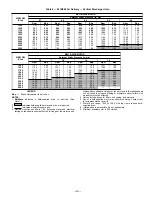
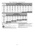
to determine fan speed settings.
For units with electric heating, required minimum cfm is 900
for 551B036; 1200 for 551B048; 1500 for 551B060; and 1800
for 551B072.
A. Belt-Drive Motors
Fan motor pulleys are factory-set for speed shown in Table 1.
Check pulley alignment and belt tension prior to start-up.
To change fan speed:
1. Shut off unit power supply.
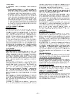
2. Loosen belt by loosening fan motor mounting nuts. See
Fig. 26.
3. Loosen movable pulley flange setscrew (see Fig. 27).
4. Screw movable flange toward fixed flange to increase speed
or away from fixed flange to decrease speed. Increasing
fan speed increases load on motor. Do not exceed maxi-
mum speed specified in Table 1.
5. Set movable flange at nearest keyway of pulley hub and
tighten setscrew. (See Table 1 for speed change for each
full turn of pulley flange.)
To align fan and motor pulleys (see Fig. 27):
1. Loosen fan pulley setscrews.
2. Slide fan pulley along fan shaft.
3. Make angular alignment by loosening motor from
mounting.
To adjust belt tension:
1. Loosen fan motor mounting nuts.
2. Slide motor mounting plate away from fan scroll for proper
belt tension (
1
⁄
2
-in. deflection with one finger).
3. Tighten motor mounting nuts.
4. Adjust bolt and tighten nut to secure motor in fixed
position.
Table 4 — Fan Rpm at Motor Pulley Settings*
UNIT
551B
MOTOR PULLEY TURNS OPEN
0
1
⁄
2
1
1
1
⁄
2
2
2
1
⁄
2
3
3
1
⁄
2
4
4
1
⁄
2
5
5
1
⁄
2
6
036
1090
1055
1025
990
960
925
890
860
825
795
760
—
—
048
1185
1150
1115
1080
1045
1015
980
945
910
875
840
—
—
060
1460
1425
1385
1350
1315
1275
1240
1205
1165
1130
1095
1050
1020
072
1585
1540
1490
1445
1400
1350
1305
1260
1210
1165
1120
—
—
*Approximate fan rpm shown.
CAPACITOR
(551B036, 048
SINGLE-PHASE
UNITS ONLY)
Fig. 26 — Belt Drive Motor Mounting
Fig. 27 — Evaporator-Fan Pulley Adjustment
—20—
Summary of Contents for 551B Series
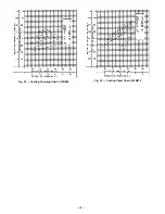
Page 32: ...Fig 34 Cooling Charging Chart 551B060 Fig 35 Cooling Chart Chart 551B072 32 ...
Page 37: ......
Page 38: ......
Page 39: ......


