background image

14

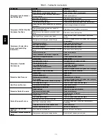
Table 1 – Cooling Service Analysis

PROBLEM

CAUSE

REMEDY

Compressor and Condenser

Fan Will Not Start.

Power failure.

Call power company.

Fuse blown or circuit breaker tripped.

Replace fuse or reset circuit breaker.

Defective thermostat, contactor, transformer,

or control relay.

Replace component.

Insufficient line voltage.

Determine cause and correct.

Incorrect or faulty wiring.

Check wiring diagram and rewire correctly.

Thermostat setting too high.

Lower thermostat setting below room temperature.

Compressor Will Not Start But

Condenser Fan Runs.

Faulty wiring or loose connections in compres-

sor circuit.

Check wiring and repair or replace.

Compressor motor burned out, seized, or

internal overload open.

Determine cause. Replace compressor.

Defective run/start capacitor, overload, start

relay.

Determine cause and replace.

One leg of three---phase power dead.

Replace fuse or reset circuit breaker. Determine

cause.

Compressor Cycles (other

than normally satisfying

thermostat).

Refrigerant overcharge or undercharge.

Recover refrigerant, evacuate system, and recharge

to nameplate.

Defective compressor.

Replace and determine cause.

Insufficient line voltage.

Determine cause and correct.

Blocked condenser.

Determine cause and correct.

Defective run/start capacitor, overload, or start

relay.

Determine cause and replace.

Defective thermostat.

Replace thermostat.

Faulty condenser---fan motor or capacitor.

Replace.

Restriction in refrigerant system.

Locate restriction and remove.

Compressor Operates

Continuously.

Dirty air filter.

Replace filter.

Unit undersized for load.

Decrease load or increase unit size.

Thermostat set too low.

Reset thermostat.

Low refrigerant charge.

Locate leak; repair and recharge.

Leaking valves in compressor.

Replace compressor.

Air in system.

Recover refrigerant, evacuate system, and recharge.

Condenser coil dirty or restricted.

Clean coil or remove restriction.

Excessive Head Pressure.

Dirty air filter.

Replace filter.

Dirty condenser coil.

Clean coil.

Refrigerant overcharged.

Recover excess refrigerant.

Air in system.

Recover refrigerant, evacuate system, and recharge.

Condenser air restricted or air short---cycling.

Determine cause and correct.

Head Pressure Too Low.

Low refrigerant charge.

Check for leaks; repair and recharge.

Compressor valves leaking.

Replace compressor.

Restriction in liquid tube.

Remove restriction.

Excessive Suction Pressure.

High head load.

Check for source and eliminate.

Compressor valves leaking.

Replace compressor.

Refrigerant overcharged.

Recover excess refrigerant.

Suction Pressure Too Low.

Dirty air filter.

Replace filter.

Low refrigerant charge.

Check for leaks; repair and recharge.

Metering device or low side restricted.

Remove source of restriction.

Insufficient evaporator airflow.

Increase air quantity. Check filter and replace if

necessary.

Temperature too low in conditioned area.

Reset thermostat.

Outdoor ambient below 25

˚

F.

Install low---ambient kit.

Evaporator Fan Will Not

Shut Off.

Time off delay not finished.

Wait for 30---second off delay.

Compressor Makes Excessive

Noise.

Compressor rotating in wrong direction.

Reverse the 3---phase power leads.

580J

Summary of Contents for 580J*04--12

Page 1: ...vailable for all brazing operations Follow all safety codes Wear safety glasses and work gloves Use quenching cloth for brazing operations Have fire extinguisher available Read these instructions thoroughly and follow all warnings or cautions attached to the unit Consult local building codes and National Electrical Code NEC for special requirements Recognize safety information This is the safety a...

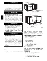
Page 2: ...pressure greater than 0 5 psig it must be replaced before use When pressure testing field supplied gas piping at pressures of 0 5 psig or less a unit connected to such piping must be isolated by closing the manual gas valve s WARNING UNIT ARRANGEMENT AND ACCESS General Fig 1 and Fig 2 show general unit arrangement and access locations FILTER ACCESS PANEL OUTDOOR AIR OPENING AND INDOOR COIL ACCESS ...

Page 3: ...milar replace ment filters of same size To re install the access panel 1 Slide the top of the panel up under the unit top panel 2 Slide the bottom into the side channels 3 Push the bottom flange down until it contacts the top of the lower panel or economizer top IMPORTANT DO NOT OPERATE THE UNIT WITHOUT THESE FILTERS Outside Air Hood Outside air hood inlet screens are permanent aluminum mesh type ...

Page 4: ...otor mounting plate front bolts and rear bolts 3 Push the motor and its mounting plate towards the blower housing as close as possible to reduce the cen ter distance between fan shaft and motor shaft 4 Remove the belt by gently lifting the old belt over one of the pulleys 5 Install the new belt by gently sliding the belt over both pulleys and then sliding the motor and plate away from the fan hous...

Page 5: ...xed pitch pulley after the final airflow balance adjustment This will reduce the amount of vibration generated by the motor belt drive system COOLING UNIT OPERATION AND SAFETY HAZARD Failure to follow this warning could cause personal injury death and or equipment damage This system uses PuronR refrigerant which has higher pressures than R 22 and other refrigerants No other refrigerant may be used...

Page 6: ... a USDA accepted biodegradable agent that will not harm the coil or surrounding components such as electrical wiring painted metal surfaces or insulation Use of non recommended coil cleaners is strongly discouraged since coil and unit durability could be affected One Row Coil Wash coil with commercial coil cleaner It is not necessary to remove top panel Two Row Coils Clean coil as follows 1 Turn o...

Page 7: ...ater using downward rinsing motion of water spray nozzle Protect fins from damage from the spray nozzle Evaporator Coil Cleaning the Evaporator Coil 1 Turn unit power off Install lockout tag Remove evaporator coil access panel 2 If economizer or two position damper is installed re move economizer by disconnecting Molex plug and removing mounting screws 3 Slide filters out of unit 4 Clean coil usin...

Page 8: ...Refrigerant Charge Amount of refrigerant charge is listed on the unit s nameplate Refer to GTAC2 5 Charging Recovery Recycling and Reclamation training manual and the following procedures Unit panels must be in place when unit is operating during the charging procedure No Charge Use standard evacuating techniques After evacuating system weigh in the specified amount of refrigerant Low Charge Cooli...

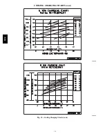
Page 9: ...9 COOLING CHARGING CHARTS C08203 C08204 Fig 12 Cooling Charging Charts 580J ...

Page 10: ...10 COOLING CHARGING CHARTS cont C08228 C08229 Fig 12 Cooling Charging Charts cont 580J ...

Page 11: ...11 COOLING CHARGING CHARTS cont C08437 C08438 Fig 12 Cooling Charging Charts cont 580J ...

Page 12: ...12 COOLING CHARGING CHARTS cont C08439 Fig 12 Cooling Charging Charts cont 580J ...

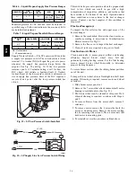
Page 13: ... the discharge pressure should rise as is normal on any start up NOTE If the suction pressure does not drop and the discharge pressure does not rise to normal levels 4 Note that the evaporator fan is probably also rotating in the wrong direction 5 Turn off power to the unit 6 Reverse any two of the unit power leads 7 Reapply power to the compressor The suction and discharge pressure levels should ...

Page 14: ...riction and remove Compressor Operates Continuously Dirty air filter Replace filter Unit undersized for load Decrease load or increase unit size Thermostat set too low Reset thermostat Low refrigerant charge Locate leak repair and recharge Leaking valves in compressor Replace compressor Air in system Recover refrigerant evacuate system and recharge Condenser coil dirty or restricted Clean coil or ...

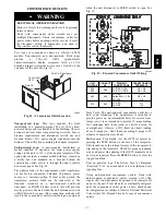
Page 15: ...connected at the line side terminals on a unit mounted non fused disconnect or HACR breaker switch this will provide service power to the unit when the unit disconnect switch or HACR switch is open Other connection methods will result in the convenience outlet circuit being de energized when the unit disconnect or HACR switch is open See Fig 15 CO8283 Fig 15 Powered Convenience Outlet Wiring UNIT ...

Page 16: ...er Assembly Sensor The sensor see Fig 17 includes a plastic housing a printed circuit board a clear plastic cover a sampling tube inlet and an exhaust tube The sampling tube when used and exhaust tube are attached during installation The sampling tube varies in length depending on the size of the rooftop unit The clear plastic cover permits visual inspections without having to disassemble the sens...

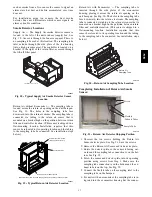
Page 17: ...shown RA detector must be moved from shipping position to operating position by installer C07307 Fig 19 Typical Return Air Detector Location Return Air with Economizer The sampling tube is inserted through the side plates of the economizer housing placing it across the return air opening on the unit basepan See Fig 20 The holes in the sampling tube face downward into the return air stream The samp...

Page 18: ...Highlight B Smoke detector NC contact set will open on smoke alarm condition de energizing the ORN conductor Highlight C 24 v power signal via ORN lead is removed at Smoke Detector input on LCTB all unit operations cease immediately Using Remote Logic Five conductors are provided for field use see Highlight D for additional annunciation functions Additional Application Data Refer to Catalog No HKR...

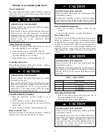
Page 19: ...s ability to initiate a dirty sensor test and indicate its results OPERATIONAL TEST HAZARD Failure to follow this caution may result in personnel and authority concern Pressing the controller s test reset switch for longer than seven seconds will put the duct detector into the alarm state and activate all automatic alarm responses CAUTION Dirty Controller Test Procedure 1 Press the controller s te...

Page 20: ...e test reset station s Alarm LED turns on 3 Reset the sensor by turning the key switch to the RESET TEST position for two seconds 4 Verify that the test reset station s Alarm LED turns off Remote Test Reset Station Dirty Sensor Test The test reset station dirty sensor test checks the test reset station s ability to initiate a sensor dirty test and indicate the results It must be wired to the contr...

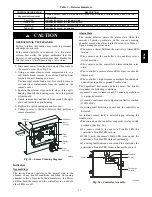
Page 21: ...ousing Sensor housing C07305 Fig 25 Sensor Cleaning Diagram Indicators Normal State The smoke detector operates in the normal state in the absence of any trouble conditions and when its sensing chamber is free of smoke In the normal state the Power LED on both the sensor and the controller are on and all other LEDs are off Alarm State The smoke detector enters the alarm state when the amount of sm...

Page 22: ...ntroller s supply input terminals If power is not present replace or re pair wiring as required Remote Test Reset Station s Trouble LED Does Not flash When Performing a Dirty Test But the Controller s Trouble LED Does 1 Verify that the remote test station is wired as shown in Fig 23 Repair or replace loose or missing wiring 2 Configure the sensor dirty test to activate the control ler s supervisio...

Page 23: ...ER SECTION C06152 Fig 27 Burner Section Details Limit Switch and Shield C08284 Fig 28 Limit Switch Location Fuel Types and Pressures Natural Gas The 580J unit is factory equipped for use with Natural Gas fuel at elevation under 2000 ft 610 m See section Orifice Replacement for information in modifying this unit for installation at elevations above 2000 ft 610 m Gas line pressure entering the unit ...

Page 24: ...mpurities additives and residues that have settled to the bottom of the tank Operation under these conditions can cause harm to the heat exchanger system Contact your fuel supplier if this condition is suspected Flue Gas Passageways To inspect the flue collector box and upper areas of the heat exchanger 1 Remove the combustion blower wheel and motor as sembly according to directions in Combustion ...

Page 25: ...manual gas valve 2 Shut off power to unit 3 Slide out burner partition 4 Disconnect gas piping at unit gas valve Orifice 1 00 in 25 4 mm Manifold Pipe C08211 Fig 32 Orifice Projection 5 Remove wires connected to gas valve Mark each wire 6 Remove igniter wires and sensor wires at the Integ rated Gas Unit Controller IGC See Fig 34 7 Remove the 2 screws that attach the burner rack to the vestibule pl...

Page 26: ...o adjust manifold pressure 5 When main burners ignite check all fittings mani fold and orifices for leaks 6 Adjust high stage pressure to specified setting by turning the plastic adjustment screw clockwise to in crease pressure counter clockwise to decrease pres sure 7 For Two Stage Gas Valves set room thermostat to call for low stage heat Adjust low stage pressure to specified setting 8 Replace r...

Page 27: ...00 BTUH INPUT 90 000BTUH INPUT AND 120 000 BTUH INPUT LOW HEAT MEDIUM AND HIGH HEAT C06154 Fig 35 Spark Adjustment 04 07 125 000 90 000 BTUH INPUT 180 000 120 000 BTUH INPUT 240 000 180 000 BTUH INPUT 250 000 200 000 BTUH INPUT C08447 Fig 36 Spark Adjustment 08 12 580J ...

Page 28: ...ble codes will be displayed in numerical sequence Indicates a code that is not an error The unit will continue to operate when this code is displayed IMPORTANT Refer to Troubleshooting Table 13 and Table 14 for additional information Orifice Replacement This unit uses orifice type LH32RFnnn where nnn indicates orifice reference size When replacing unit orifices order the necessary parts via RCD Se...

Page 29: ...Speed sensor gas section analog input J1 1 3 FS T1 Flame sensor gas section switch input W Heat stage 1 LCTB 24 VAC J2 2 RS Rollout switch gas section switch input J2 5 6 LS Limit switch fan section switch input J2 7 8 CS Centrifugal switch not used switch input J2 9 10 OUTPUTS L1 CM Induced draft combustion motor gas section line VAC IFO Indoor fan control box relay J2 1 GV Gas valve heat stage 1...

Page 30: ...RF055 0 0550 55 LH32RF052 0 0520 56 LH32RF047 0 0465 57 LH32RF043 0 0430 58 LH32RF042 0 0420 Table 11 Altitude Compensation 04 07 Small Chassis ELEVATION ft m 72 000 BTUH Nominal 115 000 BTUH Nominal 150 000 BTUH Nominal NG Orifice Size LP Orifice Size NG Orifice Size LP Orifice Size NG Orifice Size LP Orifice Size 0 2000 610 331 514 331 503 30 463 2000 610 351 514 351 514 30 473 3000 914 351 524 ...

Page 31: ...as LP Liquid Propane 1 CRLPELEV001A00 As the height above sea level increases there is less oxygen per cubic ft of air Therefore heat input rate should be reduced at higher altitudes 2 CRLPELEV002A00 3 CRLPELEV003A00 Not included in kit May be purchased separately through dealer 4 CRLPELEV004A00 Minimum heating entering air temperature When operating on first stage heating the minimum temperature ...

Page 32: ...s pressure at manifold Clock gas meter for input If too low increase manifold pressure or replace with correct orifices Unit undersized for application Replace with proper unit or add additional unit Restricted airflow Clean filter replace filter or remove any restrictions Blower speed too low Use high speed tap increase fan speed or install optional blower as suitable for individual units Limit s...

Page 33: ...ting If heat on gas valve Off and inducer On Inducer sense normal or heat call W Off Inducer sense On when heat call Off or induc er sense Off when heat call On Check wiring voltage and operation of IGC motor Check speed sensor wiring to IGC 7 Flashes Rollout Switch Lockout Gas valve and igniter Off Indoor fan and inducer On Power reset Rollout switch has opened Check gas valve operation Check ind...

Page 34: ...erature Potentiometer Defaults Settings Power Exhaust Middle Minimum Pos Fully Closed DCV Max Middle DCV Set Middle Enthalpy C Setting NOTES 1 620 ohm 1 watt 5 resistor should be removed only when using differential enthalpy or dry bulb 2 If a separate field supplied 24 v transformer is used for the IAQ sensor power supply it cannot have the secondary of the transformer grounded 3 For field instal...

Page 35: ...On On Off Modulating between min position and full open Modulating between closed and full open On Off Off Off Off Off Off Off Minimum position Closed Above set DCV LED On High Free Cooling LED Off Low On On On On Modulating between min position and DCV maximum Modulating between closed and DCV maximum On Off On Off Off Off Off Off Low Free Cooling LED On High On On On Off Modulating Modulating On...

Page 36: ...the EconoMi er IV in the outdoor airstream See Fig 44 The operating range of temperature measurement is 40_ to 100_F 4_ to 38_C Supply Air Temperature SAT Sensor The supply air temperature sensor is a 3 K thermistor located at the inlet of the indoor fan See Fig 44 This sensor is factory installed The operating range of temperature measurement is 0 to 158_F 18_ to 70_C See Table 16 for sensor temp...

Page 37: ...l The outdoor air and supply air temperature sensors are included as standard For this control mode the outdoor temperature is compared to an adjustable setpoint selected on the control If the outdoor air temperature is above the setpoint the EconoMi er IV will adjust the outside air dampers to minimum position If the outdoor air temperature is below the setpoint the position of the outside air da...

Page 38: ...e in the outside air and one in the return air duct The EconoMi er IV controller compares the outdoor air enthalpy to the return air enthalpy to determine EconoMi er IV use The controller selects the lower enthalpy air return or outdoor for cooling For example when the outdoor air has a lower enthalpy than the return air the EconoMi er IV opens to bring in outdoor air for free cooling Replace the ...

Page 39: ...urned on When there is a call for exhaust the EconoMi er IV controller provides a 45 15 second delay before exhaust fan activation to allow the dampers to open This delay allows the damper to reach the appropriate position to avoid unnecessary fan overload Minimum Position Control There is a minimum damper position potentiometer on the EconoMi er IV controller See Fig 45 The minimum damper positio...

Page 40: ...at is greater than the required ventilation rate for maximum occupancy A proportional anticipatory strategy will cause the fresh air supplied to increase as the room CO2 level increases even though the CO2 setpoint has not been reached By the time the CO2 level reaches the setpoint the damper will be at maximum ventilation and should maintain the setpoint In order to have the CO2 sensor control th...

Page 41: ... resistor and a 5 6 kilo ohm resistor which are not supplied with the EconoMi er IV IMPORTANT Be sure to record the positions of all potentiometers before starting troubleshooting 1 Disconnect power at TR and TR1 All LEDs should be off Exhaust fan contacts should be open 2 Disconnect device at P and P1 3 Jumper P to P1 4 Disconnect wires at T and T1 Place 5 6 kilo ohm resistor across T and T1 5 Ju...

Page 42: ...et DCV maximum position potentiometer to previ ous setting 4 Set minimum position DCV setpoint and exhaust po tentiometers to previous settings 5 Remove 620 ohm resistor from terminals SR and 6 Remove 1 2 kilo ohm checkout resistor from termin als SO and If used reconnect sensor from termin als SO and 7 Remove jumper from TR to N 8 Remove jumper from TR to 1 9 Remove 5 6 kilo ohm resistor from T a...

Page 43: ...l Wiring Check all electrical connections in unit control boxes Tighten as required Refrigerant Service Ports Each unit system has two 1 4 SAE flare with check valves service ports one on the suction line and one on the compressor discharge line Be sure that caps on the ports are tight Compressor Rotation On 3 phase units with scroll compressors it is important to be certain compressor is rotating...

Page 44: ... heating selector lever below room temperature will temporarily shut unit off until space temperature falls below thermostat setting Ventilation Continuous Fan Set fan and system selector switches at ON and OFF positions respectively Evaporator fan operates continuously to provide constant air circulation When the evaporator fan selector switch is turned to the OFF position there is a 30 second de...

Page 45: ...be accompanied by economizer dampers moving to Minimum Position setpoint for ventilation If indoor fan is off dampers will close During Unoccupied mode operation dampers will remain closed unless a DCV demand is received When the room temperature calls for heat W1 closes the heating controls are energized as described in Heating Unit Without Economizer above Demand Controlled Ventilation If a fiel...

Page 46: ...46 C08308 Fig 52 580J Typical Unit Wiring Diagram Power 06A B C 208 230 3 60 580J ...

Page 47: ...47 C08317 Fig 53 580J Unit Wiring Diagram Control 06A B C 580J ...

Page 48: ... HX heat L Enthalpy econo w baro relief CO2 1 Q Motorized 2 pos damper w baro relief Heat Level 060 60 000 Indoor Fan Options 072 72 000 1 Standard static option 090 90 000 2 Medium static option 115 115 000 3 High static option 120 120 000 150 150 000 Coil Options Indoor Coil Outdoor Coil A Al Cu Al Cu B Precoat Al Cu Al Cu C E coat Al Cu Al Cu D E coat Al Cu E coat Al Cu E Cu Cu Al Cu F Cu Cu Cu...

Page 49: ...Diameter in 10 x 10 10 x 10 10 x 10 10 x 10 Medium Static 1 phase Motor Qty Drive Type 1 Belt 1 Belt 1 Belt Max BHP 1 2 1 2 1 5 RPM Range 770 1175 770 1175 1035 1466 Motor Frame Size 48 56 56 Fan Qty Type 1 Centrifugal 1 Centrifugal 1 Centrifugal Fan Diameter in 10 x 10 10 x 10 10 x 10 Medium Static 3 phase Motor Qty Drive Type 1 Belt 1 Belt 1 Belt 1 Belt Max BHP 1 2 1 2 2 4 2 9 RPM Range 770 1175...

Page 50: ...al 1 Centrifugal 1 Centrifugal Fan Diameter in 15 x 15 15 x 15 15 x 15 Medium Static 3 phase Motor Qty Drive Type 1 Belt 1 Belt 1 Belt Max BHP 2 9 2 4 3 7 RPM Range 733 949 690 936 838 1084 Motor Frame Size 56 56 56 Fan Qty Type 1 Centrifugal 1 Centrifugal 1 Centrifugal Fan Diameter in 15 x 15 15 x 15 15 x 15 High Static 3 phase Motor Qty Drive Type 1 Belt 1 Belt 1 Belt Max BHP 5 25 3 7 5 25 RPM R...

Page 51: ...burners total 1 or 2 3 1 or 2 3 1 or 2 3 Rollout switch opens Closes 195 115 195 115 195 115 Temperature rise 50 80 50 80 50 80 Liquid Propane Heat LOW of stages of burners total 1 2 1 2 1 2 1 2 Rollout switch opens Closes 195 115 195 115 195 115 195 115 Temperature rise 25 55 25 55 25 55 25 55 MED of stages of burners total 1 or 2 3 1 or 2 3 1 or 2 3 1 or 2 3 Rollout switch opens Closes 195 115 1...

Page 52: ...max 50 80 50 80 50 80 Liquid Propane Heat Connection size 1 2 NPT 1 2 NPT 1 2 NPT 1 2 NPT LOW of stages of burners total 1 2 1 2 1 2 1 2 Rollout switch opens Closes 195 115 195 115 195 115 195 115 Temperature rise min max 25 55 25 55 25 55 25 55 Connection size 1 2 NPT 1 2 NPT 1 2 NPT 1 2 NPT MED of stages of burners total 1 or 2 3 1 or 2 3 1 or 2 3 1 or 2 3 Rollout switch opens Closes 195 115 195...

Page 53: ...s or accessories 3 Tabular data accounts for pressure loss due to clean filters unit casing and wet coils Factory options and accessories may add static pressure losses 4 The Fan Performance tables offer motor drive recommendations In cases when two motor drive combinations would work Bryant recommended the lower horsepower option 5 For information on the electrical properties of Bryant s motors p...

Page 54: ...g field supplied motor pulley part number KR11HY161 and belt part number KR30AE035 580J 04 1 Phase 3 Ton Vertical Supply CFM AVAILABLE EXTERNAL STATIC PRESSURE in wg 0 2 0 4 0 6 0 8 1 0 RPM BHP RPM BHP RPM BHP RPM BHP RPM BHP Field Supplied Drive1 Standard Static Option Medium Static Option 900 567 0 15 688 0 22 786 0 30 871 0 37 947 0 44 975 591 0 17 710 0 26 807 0 34 891 0 42 966 0 49 1050 615 0...

Page 55: ...Recommend using field supplied drive part number KR11AG006 and belt part number KR30AE039 580J 04 3 Phase 3 Ton Vertical Supply CFM AVAILABLE EXTERNAL STATIC PRESSURE in wg 0 2 0 4 0 6 0 8 1 0 RPM BHP RPM BHP RPM BHP RPM BHP RPM BHP Field Supplied Drive1 Standard Static Option Medium Static Option 900 567 0 15 688 0 22 786 0 30 871 0 37 947 0 44 975 591 0 17 710 0 26 807 0 34 891 0 42 966 0 49 105...

Page 56: ...ed 1 Recommend using field supplied motor pulley part number KR11HY161 and belt part number KR30AE035 580J 05 1 Phase 4 Ton Vertical Supply CFM AVAILABLE EXTERNAL STATIC PRESSURE in wg 0 2 0 4 0 6 0 8 1 0 RPM BHP RPM BHP RPM BHP RPM BHP RPM BHP Standard Static Option Medium Static Option 1200 666 0 26 778 0 37 871 0 47 952 0 57 1025 0 67 1300 701 0 31 810 0 43 901 0 54 981 0 65 1053 0 76 1400 737 ...

Page 57: ...ecommend using field supplied fan pulley part no KR11AZ506 motor pulley part no KR11HY181 and belt part no KR30AE041 580J 05 3 Phase 4 Ton Vertical Supply CFM AVAILABLE EXTERNAL STATIC PRESSURE in wg 0 2 0 4 0 6 0 8 1 0 RPM BHP RPM BHP RPM BHP RPM BHP RPM BHP Standard Static Option Medium Static Option 1200 666 0 26 778 0 37 871 0 47 952 0 57 1025 0 67 1300 701 0 31 810 0 43 901 0 54 981 0 65 1053...

Page 58: ... Fan Performance Notes on page 53 Boldface indicates field supplied drive is required 580J 06 1 Phase 5 Ton Vertical Supply CFM AVAILABLE EXTERNAL STATIC PRESSURE in wg 0 2 0 4 0 6 0 8 1 0 RPM BHP RPM BHP RPM BHP RPM BHP RPM BHP Standard Static Option Medium Static Option 1500 848 0 42 968 0 55 1069 0 68 1158 0 80 1238 0 94 1625 897 0 51 1013 0 65 1111 0 79 1198 0 93 1277 1 07 1750 947 0 61 1059 0...

Page 59: ...ired 1 Recommend using field supplied fan pulley part number KR11AZ506 motor pulley part number KR11HY191 and belt part number KR30AE042 580J 06 3 Phase 5 Ton Vertical Supply CFM AVAILABLE EXTERNAL STATIC PRESSURE in wg 0 2 0 4 0 6 0 8 1 0 RPM BHP RPM BHP RPM BHP RPM BHP RPM BHP Standard Static Option Medium Static Option 1500 848 0 42 968 0 55 1069 0 68 1158 0 80 1238 0 94 1625 897 0 51 1013 0 65...

Page 60: ...end using field supplied fan pulley part number KR11AZ406 motor pulley part number KR11HY151 and belt part number KR29AF035 580J 07 3 Phase 6 Ton Vertical Supply CFM AVAILABLE EXTERNAL STATIC PRESSURE in wg 0 2 0 4 0 6 0 8 1 0 RPM BHP RPM BHP RPM BHP RPM BHP RPM BHP Standard Static Option Medium Static Option 1800 967 0 63 1075 0 80 1170 0 97 1255 1 13 1333 1 28 1950 1029 0 77 1132 0 96 1223 1 14 ...

Page 61: ... field supplied drive is required 1 Recommend using field supplied fan pulley part no KR11AZ002 and belt part no KR29AF054 580J 08 3 PHASE 7 5 TON VERTICAL SUPPLY CFM AVAILABLE EXTERNAL STATIC PRESSURE in wg 0 2 0 4 0 6 0 8 1 0 RPM BHP RPM BHP RPM BHP RPM BHP RPM BHP Standard Static Option Medium Static Option 2250 513 0 54 595 0 76 665 1 01 728 1 27 786 1 56 2438 541 0 65 620 0 89 688 1 14 750 1 ...

Page 62: ...plied fan pulley part no KR11AK012 and belt part no KR29AF055 2 Recommend using field supplied motor pulley part no KR11HY310 fan pulley part no KR11AZ002 and belt part no KR29AF054 580J 09 3 PHASE 8 5 TON VERTICAL SUPPLY CFM AVAILABLE EXTERNAL STATIC PRESSURE in wg 0 2 0 4 0 6 0 8 1 0 RPM BHP RPM BHP RPM BHP RPM BHP RPM BHP Standard Static Option Medium Static Option 2550 526 0 51 600 0 65 666 0 ...

Page 63: ... supplied drive is required 1 Recommend using field supplied fan pulley part no KR11AD912 and belt part no KR29AF051 2 Recommend using field supplied motor pulley part no KR11HY410 580J 12 3 PHASE 10 TON VERTICAL SUPPLY CFM AVAILABLE EXTERNAL STATIC PRESSURE in wg 0 2 0 4 0 6 0 8 1 0 RPM BHP RPM BHP RPM BHP RPM BHP RPM BHP Standard Static Option Medium Static Option 3000 616 0 79 689 0 97 757 1 16...

Page 64: ...380 1337 1294 1251 1207 1164 1121 1078 1035 High Static 3 phase Standard Static 1175 1135 1094 1054 1013 973 932 892 851 811 770 Medium Static 1466 1423 1380 1337 1294 1251 1207 1164 1121 1078 1035 High Static 1687 1649 1610 1572 1533 1495 1457 1418 1380 1341 1303 07 3 phase Standard Static 1457 1419 1380 1342 1303 1265 1227 1188 1150 1111 1073 Medium Static 1518 1484 1449 1415 1380 1346 1311 1277...

Page 65: ...75 3 60 518 633 3 8 37 325 0 6 Std Static 1000 2 0 71 1 9 Med Static 2120 2 1 80 2 0 High Static 2120 2 1 80 2 0 580J 05 4 TONS V Ph Hz VOLTAGE COMP ea OFM ea IFM RANGE RLA LRA WATTS FLA TYPE Max WATTS Max AMP Draw EFF at Full Load FLA MIN MAX 208 1 60 187 253 21 8 117 325 1 5 Std Static 1000 5 1 70 4 9 Med Static 1850 7 4 78 7 0 230 1 60 187 253 21 8 117 325 1 5 Std Static 1000 5 1 70 4 9 Med Sta...

Page 66: ...325 0 8 Std Static 2120 2 7 80 2 6 Med Static 2615 3 6 81 3 4 High Static 2615 3 6 81 3 4 575 3 60 518 633 5 8 39 325 0 6 Std Static 2120 2 1 80 2 0 Med Static 3775 2 9 81 2 8 High Static 3775 2 9 81 2 8 580J 07 6 TONS V Ph Hz VOLTAGE COMP ea OFM ea IFM RANGE RLA LRA WATTS FLA TYPE Max WATTS Max AMP Draw EFF at Full Load FLA MIN MAX 208 3 60 187 253 19 0 12 325 1 5 Std Static 2120 5 5 80 5 2 Med S...

Page 67: ...5 80 5 2 Med Static 2120 5 5 80 5 2 High Static 2694 10 5 80 10 0 230 3 60 187 253 29 5 195 325 1 5 Std Static 1448 5 5 80 5 2 Med Static 2120 5 5 80 5 2 High Static 2694 10 5 80 10 0 460 3 60 414 506 14 7 95 325 0 8 Std Static 1448 2 7 80 2 6 Med Static 2120 2 7 80 2 6 High Static 2694 4 6 80 4 4 575 3 60 518 633 12 2 80 325 0 6 Std Static 1379 2 5 80 2 4 Med Static 1390 2 1 80 2 0 High Static 37...

Page 68: ...460 3 60 STD 0 25 1 0 10 7 15 0 10 49 11 7 15 0 12 50 MED 10 7 15 0 10 49 11 7 15 0 12 50 HIGH 11 2 15 0 11 58 12 2 15 0 12 59 575 3 60 STD 0 24 1 9 8 5 15 0 8 44 10 4 15 0 11 46 MED 8 5 15 0 8 44 10 4 15 0 11 46 HIGH 8 6 15 0 9 50 10 5 15 0 11 52 580J 06 208 230 1 60 STD 0 48 1 9 39 2 60 0 37 150 41 1 60 0 40 152 MED 41 3 60 0 40 175 43 2 60 0 42 177 208 230 3 60 STD 0 48 1 9 25 9 30 0 25 126 27 ...

Page 69: ...28 157 HIGH 29 9 45 30 159 31 7 45 32 161 575 3 60 STD 0 24 3 8 18 5 30 18 95 22 3 30 22 99 MED 19 3 30 19 106 23 1 30 23 110 HIGH 22 1 30 22 120 25 9 30 26 124 1Fuse or breaker LEGEND CO Convenient outlet DISC Disconnect FLA Full load amps IFM Indoor fan motor LRA Locked rotor amps MCA Minimum circuit amps MOCP Maximum over current protection PE Power exhaust UNPWRD CO Unpowered convenient outlet...

Page 70: ...30 3 60 48TM500213 05 48TM500748 08 460 3 60 48TM500213 05 48TM500748 08 575 3 60 48TM500213 05 48TM500215 08 07 208 230 3 60 48TM500213 05 48TM500748 08 460 3 60 48TM500213 05 48TM500748 08 575 3 60 48TM500213 05 48TM500215 08 08 208 230 3 60 48TM500929 05 48TM500803 05 460 3 60 48TM500929 05 48TM500803 05 575 3 60 48TM500929 05 48TM500804 05 09 208 230 3 60 48TM500929 05 48TM500803 05 460 3 60 4...

Page 71: ...TORMASTER SENSOR LOCATIONS C08259 Fig 54 580J 04 A B C Outdoor Circuiting C08260 Fig 55 580J 05 06 A B C Outdoor Circuiting C08261 Fig 56 580J 07 A C Outdoor Circuiting C08262 Fig 57 580J 08 A C Outdoor Circuiting 580J ...

Page 72: ...Manufacturer reserves the right to discontinue or change at any time specifications or designs without notice and without incurring obligations E2008 Bryant Heating Cooling Systems D 7310 W Morris St D Indianapolis IN 46231 Printed in U S A Edition Date 07 08 Replaces NEW Catalog No SM580J 01 580J ...

Page 73: ... IS TIGHT j VERIFY PULLEY ALIGNMENT AND BELT TENSION ARE CORRECT III START UP ELECTRICAL SUPPLY VOLTAGE L1 L2 L2 L3 L3 L1 COMPRESSOR AMPS L1 L2 L2 INDOOR FAN AMPS L1 L2 L2 TEMPERATURES OUTDOOR AIR TEMPERATURE DB WB RETURN AIR TEMPERATURE DB WB COOLING SUPPLY AIR DB WB GAS HEAT SUPPLY AIR DB PRESSURES GAS INLET PRESSURE IN WG GAS MANIFOLD PRESSURE IN WG LOW FIRE IN WG HI FIRE REFRIGERANT SUCTION PS...

Reviews: