background image

581J

GAS HEAT/ELECTRIC COOLING

PACKAGED ROOFTOP

3 to 8.5 NOMINAL TONS

Product Data

TM

C10405

the environmentally sound refrigerant

C10222

Manufacturer reserves the right to discontinue, or change at any time, specifications or designs without notice and without incurring obligations.

E

2010 Bryant Heating & Cooling Systems

D

7310 W. Morris St.

D

Indianapolis, IN 46231

Printed in U.S.A.

Edition Date: 4/10

Replaces: NEW

Catalog No.PDS581J---01

Summary of Contents for 581J

Page 1: ...und refrigerant C10222 Manufacturer reserves the right to discontinue or change at any time specifications or designs without notice and without incurring obligations E2010 Bryant Heating Cooling Systems D 7310 W Morris St D Indianapolis IN 46231 Printed in U S A Edition Date 4 10 Replaces NEW Catalog No PDS581J 01 ...

Page 2: ...t Bryant 3 8 5 ton 581J rooftops fit on existing Bryant curbs dating back to 1989 Also our large control box gives you room to work and room to mount Bryant accessory controls Easy to maintain Easy access handles by Bryant provide quick and easy access to all normally serviced components Our no strip screw system has superior holding power and guides screws into position while preventing the screw...

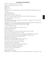
Page 3: ...g no strip screw feature on unit access panels S Two inch disposable return air filters S Tool less filter access door S Belt drive evaporator fan motor and pulley combinations available on all three phase models S Electric Drive x13 5 speed torque motor on 04 to 06 models S New terminal board facilitating simple safety circuit troubleshooting and simplified control box arrangement S Field Convert...

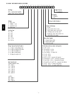
Page 4: ...n Options 09 8 5 Ton 1 Standard static option 2 Medium static option 3 High static option Refrig System Gas Heat Options Coil Options outdoor indoor hail guard A 1 Stage Cooling Nat gas heat A Al Cu Al Cu B 1 Stage Cooling Low NOx heat B Precoat Al Cu Al Cu C 1 Stage CoolingSS HX C E coat Al Cu Al Cu D 2 Stage Cooling 08 09 D E coat Al Cu E coat Al Cu F 2 Stage Cooling SS HX E Cu Cu Al Cu F Cu Cu ...

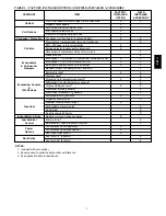
Page 5: ...s X X Motorized 2 position outdoor air damper X X Manual outdoor air damper 25 and 50 X Barometric relief1 X X Power exhaust X Economizer Sensors IAQ Devices Single dry bulb temperature sensors2 X X Differential dry bulb temperature sensors2 X Single enthalpy sensors2 X X Differential enthalpy sensors2 X Wall or duct mounted CO2 sensor2 X Unit mounted CO2 sensor2 X Gas Heat Propane conversion kit ...

Page 6: ...ience Outlet powered or un powered Reduce service and or installation costs by including a convenience outlet in your specification Bryant will install this service feature at our factory Provides a convenient 15 amp 115v GFCI receptacle with Wet in Use cover The powered option allows the installer to power the outlet from the line side of the disconnect or load side as required by code The unpowe...

Page 7: ...ting the flue discharge upwards the deflector minimizes the chance for a neighboring unit to intake the flue exhaust Optional Stainless Steel Heat Exchanger The stainless steel heat exchanger option provides the tubular heat exchanger be made out of a minimum 20 gauge type 409 stainless steel for applications where the mixed air to the heat exchanger is expected to drop below 45_F 7_C Stainless st...

Page 8: ...tio SEER Seasonal Energy Efficiency Ratio Use of the AHRI Certified TM Mark indicates a manufacturer s participation in the program For verification of certification for individual products go to www ahridirectory org NOTES 1 Rated in accordance with AHRI Standards 210 240 04 06 size and 340 360 07 09 size 2 Ratings are based on Cooling Standard 80_F 27_C db 67_F 19_C wb indoor air temp and 95_F 3...

Page 9: ...D 82 66 115 93 30 65 81 N A HIGH 120 96 150 120 40 80 80 N A 07 LOW 50 41 72 59 15 55 82 N A MED 90 73 125 103 20 50 82 N A HIGH 105 84 150 120 30 60 81 N A 08 LOW 90 73 125 103 20 50 82 N A MED 120 98 180 148 35 65 82 N A HIGH 180 147 224 184 45 75 82 N A 09 LOW 90 73 125 103 20 50 82 N A MED 120 98 180 148 30 65 82 N A HIGH 180 147 224 184 40 75 82 N A NOTES Heat ratings are for natural gas heat...

Page 10: ... 76 78 2 78 0 74 2 73 3 70 6 66 0 62 4 56 9 05A 1 78 84 7 83 6 77 1 74 6 72 3 68 3 64 7 60 9 06A 1 77 87 5 82 5 76 1 73 6 71 3 67 1 64 1 60 0 07A 1 82 90 1 82 6 81 0 79 4 77 0 73 0 70 4 66 7 08D 2 82 90 6 84 3 80 2 79 3 77 1 72 2 67 4 63 7 09D 2 82 88 6 85 0 81 6 79 5 77 4 74 1 71 0 66 3 LEGEND dB Decibel Use of the AHRI Certified TM Mark indicates a manufacturer s participation in the program For...

Page 11: ...00 1500 990 2190 MED 1000 1550 HIGH 581J 05 LOW 1200 2000 990 2190 MED 1330 2460 HIGH 1390 2220 581J 06 LOW 1500 2500 990 2730 MED 1330 2880 HIGH 1390 2780 581J 07 LOW 1800 3000 990 3640 MED 1330 4750 HIGH 1390 3750 581J 08 LOW 2250 3750 1900 4750 MED 2100 3900 HIGH 2270 3780 581J 09 LOW 2550 4250 1900 4750 MED 2100 4560 HIGH 2270 4250 581J ...

Page 12: ...0 600 1200 1073 1457 Motor Frame Size 48 48 48 56 Fan Qty Type 1 Centrifugal 1 Centrifugal 1 Centrifugal 1 Centrifugal Fan Diameter in 10 x 10 10 x 10 11 x 10 10 x 10 Medium Static 3 phase Motor Qty Drive Type 1 Belt 1 Belt 1 Belt 1 Belt Max BHP 1 2 1 7 2 4 2 9 RPM Range 770 1175 920 1303 1035 1466 1173 1518 Motor Frame Size 48 56 56 56 Fan Qty Type 1 Centrifugal 1 Centrifugal 1 Centrifugal 1 Cent...

Page 13: ...nnection size 1 2 NPT 1 2 NPT 1 2 NPT 1 2 NPT Rollout switch opens closes 195 115 195 115 195 115 195 115 Temperature rise range F 55 85 35 65 30 65 20 50 Connection size 1 or 2 3 1 or 2 3 2 4 HIGH of stages of burners total 1 2 NPT 1 2 NPT 3 4 NPT Rollout switch opens closes 195 115 195 115 195 115 Temperature rise range F 50 80 40 80 30 60 Low NOx Gas Heat of stages of burners total 1 or 2 2 1 o...

Page 14: ...ize 56 56 Fan Qty Type 1 Centrifugal 1 Centrifugal Fan Diameter in 15 x 15 15 x 15 Medium Static 3 phase Motor Qty Drive type 1 Belt 1 Belt Max BHP 2 4 2 4 RPM range 690 936 690 936 motor frame size 56 56 Fan Qty Type 1 Centrifugal 1 Centrifugal Fan Diameter in 15 x 15 15 x 15 High Static 3 phase Motor Qty Drive type 1 Belt 1 Belt Max BHP 3 7 3 7 RPM range 838 1084 838 1084 motor frame size 56 56 ...

Page 15: ... 0 14 0 14 Natural Gas Propane Heat of stages of burners total 2 3 2 3 LOW Connection size 1 2 NPT 1 2 NPT Rollout switch opens closes 195 115 195 115 Temperature rise range F 20 50 20 50 of stages of burners total 2 4 2 4 MED Connection size 3 4 NPT 3 4 NPT Rollout switch opens closes 195 115 195 115 Temperature rise range F 35 65 30 65 of stages of burners total 2 5 2 5 HIGH Connection size 3 4 ...

Page 16: ...9 1 2 494 6 5 8 168 4 5 8 118 K 46 3 4 1187 3 3 4 95 CONDENSER COIL LEFT ELECTRICAL DISCONNECT LOCATION A B G D OPTIONAL FACTORY INSTALLED CONVENIENCE OUTLET 2 5 8 67 BACK INDOOR COIL ACCESS PANEL FILTER ACCESS PANEL TOOL LESS TYP CURB WIDTH COMP ACCESS PANEL CONDENSER COIL CONNECTION SIZES A 1 3 8 35 DIA FIELD POWER SUPPLY HOLE B 2 50 DIA POWER SUPPLY KNOCKOUT C 1 3 4 51 DIA GAUGE ACCESS PLUG D 7...

Page 17: ...LOC DIMENSION CONDITION A 48 1219 mm Unit disconnect is mounted on panel 18 457 mm No disconnect convenience outlet option 18 457 mm Recommended service clearance 12 305 mm Minimum clearance B 42 1067 mm Surface behind servicer is grounded e g metal masonry wall 36 914 mm Surface behind servicer is electrically non conductive e g wood fiberglass Special Check for sources of flue products within 10...

Page 18: ...1 CRRFCURB001A01 1 2 356 2 0 610 581J 04 06 NOTES 1 Roof curb accessory is shipped disassembled 2 Insulated panels 3 Dimensions in are in millimeters 4 Roof curb galvanized steel 5 Attach ductwork to curb flanges of duct rest on curb 6 Service clearance 4 ft on each side 7 Direction of airflow 8 Connector package CRBTMPWR001A01 is for thru the curb type gas CRBTMPWR003A01 is for thru the base type...

Page 19: ...19 CURBS WEIGHTS DIMENSIONS 581J07 09 581J 07A 581J 08D 581J 09D 581J 581J 581J 36 3 8 36 3 8 924 924 C10425 Fig 5 Dimensions 581J07 09 581J ...

Page 20: ...all 36 914 mm Surface behind servicer is electrically non conductive e g wood fiberglass Special Check for sources of flue products within 10 ft of unit fresh air intake hood C 36 914 mm Side condensate drain is used 18 457 mm Minimum clearance D 48 1219 mm No flue discharge accessory installed surface is combustible material 42 1067 mm Surface behind servicer is grounded e g metal masonry wall an...

Page 21: ...CURBS WEIGHTS DIMENSIONS 581J07 09 cont 581J A07 581J D08 09 UNIT SIZE ROOFCURB ACCESSORY CRRFCURB003A01 CRRFCURB004A01 1 2 356 A 2 0 610 Typical Corner Fastening Device C10424 Fig 8 Roof Curb Details 581J ...

Page 22: ... Cond Evaporator Coils 60 27 130 59 150 68 165 75 185 88 195 88 Roof Curb 14 in curb 115 52 115 52 115 52 115 52 143 65 143 65 Roof Curb 24 in curb 197 89 197 89 197 89 197 89 245 111 245 111 CO2 sensor 5 2 5 2 5 2 5 2 5 2 5 2 Flue Discharge Deflector 7 3 7 3 7 3 7 3 7 3 7 3 Optional Indoor Motor Drive 10 5 10 5 10 5 10 5 15 7 15 7 Motor Master Controller 35 16 35 16 35 16 35 16 35 16 35 16 Return...

Page 23: ...trategies Economizers reduce operating expenses and compressor run time by providing a free source of cooling and a means of ventilation to match application changing needs In fact they should be considered for most applications Also consider the various economizer control methods and their benefits as well as sensors required to accomplish your application goals Please contact your local Bryant r...

Page 24: ...or even slightly undersize air conditioners Correctly sizing an air conditioner controls humidity better promotes efficiency reduces utility bills extends equipment life and maintains even comfortable temperatures Please contact your local Bryant representative for assistance Low ambient applications The optional Bryant economizer can adequately cool your space by bringing in fresh cool outside ai...

Page 25: ...P 0 8 RPM 712 BHP 1 17 X Convert BHP Step VIII into fan motor heat Fan motor heat 2 546 BHP Motor Eff 4 Fan motor heat 3 7 MBH XI Calculate RTU heating capacity Building heating load 85 0 MBH Fan motor heat 3 7 MBH Required heating capacity 81 3 MBH XII Select a gas heater Table 4 shows the heating capacities of the 581JEA07 103 0 MBH Select the 581JEA07 XIII Determine electrical requirements Tabl...

Page 26: ... 26 6 32 4 38 1 25 2 30 6 36 1 23 6 28 7 33 9 67 TC 39 3 39 3 39 3 37 3 37 3 37 3 35 2 35 2 35 2 32 9 32 9 32 9 30 5 30 5 31 6 SHC 23 1 29 1 35 2 22 3 28 3 34 4 21 4 27 5 33 5 20 5 26 6 32 6 19 5 25 6 31 6 72 TC 42 9 42 9 42 9 40 8 40 8 40 8 38 5 38 5 38 5 36 1 36 1 36 1 33 4 33 4 33 4 SHC 17 3 23 4 29 5 16 6 22 6 28 7 15 7 21 8 27 9 14 8 20 9 27 0 13 9 19 9 26 0 78 TC 45 9 45 9 43 7 43 7 41 3 41 ...

Page 27: ... 35 8 43 7 51 7 33 9 41 4 48 9 31 8 38 8 45 9 67 TC 53 3 53 3 53 3 50 6 50 6 50 6 47 7 47 7 47 7 44 6 44 6 44 6 41 2 41 2 42 6 SHC 31 0 39 2 47 5 29 9 38 1 46 3 28 7 37 0 45 2 27 5 35 7 43 9 26 2 34 4 42 6 72 TC 58 4 58 4 58 4 55 4 55 4 55 4 52 3 52 3 52 3 48 9 48 9 48 9 45 2 45 2 45 2 SHC 23 4 31 7 39 9 22 3 30 6 38 8 21 1 29 4 37 6 19 9 28 2 36 4 18 6 26 8 35 1 78 TC 62 7 62 7 59 5 59 5 56 1 56 ...

Page 28: ...6 50 6 59 6 47 4 47 4 55 8 SHC 48 3 58 8 69 2 46 3 56 3 66 3 44 0 53 6 63 1 41 6 50 6 59 6 39 0 47 4 55 8 67 TC 63 8 63 8 63 8 60 4 60 4 60 4 56 9 56 9 57 3 53 1 53 1 55 8 49 1 49 1 54 1 SHC 38 6 49 3 60 1 37 3 48 0 58 7 35 9 46 6 57 3 34 4 45 1 55 8 32 8 43 4 54 1 72 TC 69 6 69 6 69 6 65 9 65 9 65 9 62 1 62 1 62 1 57 9 57 9 57 9 53 5 53 5 53 5 SHC 28 4 39 1 49 9 27 0 37 8 48 6 25 7 36 4 47 2 24 2...

Page 29: ... 65 2 76 6 50 9 61 8 72 6 48 58 2 68 4 67 THC 78 9 78 9 78 9 75 2 75 2 75 2 71 2 71 2 71 2 66 8 66 8 66 8 62 62 63 4 SHC 46 5 58 4 70 3 45 56 9 68 8 43 4 55 3 67 2 41 6 53 5 65 4 39 7 51 6 63 4 72 THC 86 6 86 6 86 6 82 7 82 7 82 7 78 3 78 3 78 3 73 6 73 6 73 6 68 4 68 4 68 4 SHC 35 2 47 2 59 2 33 7 45 7 57 7 32 1 44 1 56 30 4 42 3 54 3 28 5 40 5 52 4 78 THC 93 3 93 3 89 89 84 4 84 4 79 3 79 3 73 7...

Page 30: ... 9 77 8 91 6 60 2 73 3 86 4 67 THC 98 1 98 1 98 1 93 3 93 3 93 3 88 2 88 2 88 2 82 8 82 8 83 6 77 77 81 3 SHC 58 4 74 1 89 9 56 5 72 2 87 9 54 4 70 1 85 8 52 3 67 9 83 6 50 65 6 81 3 72 THC 107 3 107 3 107 3 102 1 102 1 102 1 96 5 96 5 96 5 90 6 90 6 90 6 84 3 84 3 84 3 SHC 43 5 59 3 75 1 41 6 57 3 73 1 39 5 55 3 71 1 37 4 53 2 69 35 2 50 9 66 7 76 THC 115 2 115 2 109 5 109 5 103 5 103 5 97 2 97 2...

Page 31: ... 67 THC 109 1 109 1 109 1 103 6 103 6 103 6 97 8 97 8 97 8 91 6 91 6 93 7 85 85 90 9 SHC 65 6 83 2 100 8 63 4 81 98 6 61 78 6 96 2 58 6 76 1 93 7 55 9 73 4 90 9 72 THC 119 3 119 3 119 3 113 3 113 3 113 3 107 107 107 100 3 100 3 100 3 93 93 93 SHC 48 7 66 4 84 1 46 5 64 2 81 8 44 2 61 8 79 5 41 8 59 4 77 1 39 2 56 9 74 5 76 THC 128 128 121 5 121 5 114 7 114 7 107 5 107 5 99 8 99 8 SHC 52 6 70 6 50 ...

Page 32: ... available through your salesperson to help you select the best motor drive combination for your application 4 The Fan Performance tables offer motor drive recommendations In cases when two motor drive combinations would work Bryant recommended the lower horsepower option 5 For information on the electrical properties of Bryant motors please see the Electrical information section of this book 6 Fo...

Page 33: ...ates field supplied drive is required Medium static 770 1175 RPM 1 2 BHP max High static 1035 1466 RPM 2 4 BHP max TABLE 20 581J 04 3 PHASE 3 TON VERTICAL SUPPLY CFM Available External Static Pressure in wg 0 2 0 4 0 6 0 8 1 0 1 2 1 4 1 6 1 8 2 0 RPM BHP RPM BHP RPM BHP RPM BHP RPM BHP RPM BHP RPM BHP RPM BHP RPM BHP RPM BHP 900 592 0 14 721 0 25 826 0 38 916 0 53 997 0 69 1070 0 88 1137 1 07 1201...

Page 34: ...icates field supplied drive is required Medium static 920 1303 RPM 1 7 BHP max High static 1208 1639 RPM 2 9 BHP max TABLE 22 581J 05 3 PHASE 4 TON VERTICAL SUPPLY CFM Available External Static Pressure in wg 0 2 0 4 0 6 0 8 1 0 1 2 1 4 1 6 1 8 2 0 RPM BHP RPM BHP RPM BHP RPM BHP RPM BHP RPM BHP RPM BHP RPM BHP RPM BHP RPM BHP 1200 693 0 25 813 0 37 913 0 51 999 0 67 1077 0 84 1148 1 03 1214 1 23 ...

Page 35: ...ndicates field supplied drive is required Medium static 1035 1466 RPM 2 4 BHP High static 1303 1687 RPM 2 9 BHP max TABLE 24 581J 06 3 PHASE 5 TON VERTICAL SUPPLY CFM Available External Static Pressure in wg 0 2 0 4 0 6 0 8 1 0 1 2 1 4 1 6 1 8 2 0 RPM BHP RPM BHP RPM BHP RPM BHP RPM BHP RPM BHP RPM BHP RPM BHP RPM BHP RPM BHP 1500 847 0 41 966 0 55 1067 0 68 1158 0 81 1240 0 93 1316 1 05 1387 1 17...

Page 36: ...andard static 489 747 RPM 1 7 BHP max Medium static 733 949 RPM 2 9 BHP max High static 909 1102 RPM 4 7 BHP max TABLE 26 581J 07 3 PHASE 6 TON VERTICAL SUPPLY CFM Available External Static Pressure in wg 0 2 0 4 0 6 0 8 1 0 1 2 1 4 1 6 1 8 2 0 RPM BHP RPM BHP RPM BHP RPM BHP RPM BHP RPM BHP RPM BHP RPM BHP RPM BHP RPM BHP 1800 449 0 34 539 0 53 615 0 75 681 0 99 742 1 26 797 1 54 848 1 84 896 2 1...

Page 37: ...Standard static 518 733 RPM 1 7 BHP max Medium static 690 936 RPM 2 4 BHP max High static 838 1084 RPM 3 7 BHP max TABLE 28 581J 08 3 PHASE 7 5 TON VERTICAL SUPPLY CFM Available External Static Pressure in wg 0 2 0 4 0 6 0 8 1 0 1 2 1 4 1 6 1 8 2 0 RPM BHP RPM BHP RPM BHP RPM BHP RPM BHP RPM BHP RPM BHP RPM BHP RPM BHP RPM BHP 2250 505 0 39 595 0 54 676 0 69 750 0 86 819 1 03 884 1 21 945 1 40 100...

Page 38: ...ed Standard static 518 733 RPM 1 7 BHP max Medium static 690 936 RPM 2 4 BHP max High static 838 1084 RPM 3 7 BHP max TABLE 30 581J 09 3 PHASE 8 5 TON VERTICAL SUPPLY CFM Available External Static Pressure in wg 0 2 0 4 0 6 0 8 1 0 1 2 1 4 1 6 1 8 2 0 RPM BHP RPM BHP RPM BHP RPM BHP RPM BHP RPM BHP RPM BHP RPM BHP RPM BHP RPM BHP 2250 505 0 39 595 0 54 676 0 69 750 0 86 819 1 03 884 1 21 945 1 40 ...

Page 39: ... 1425 0 31 0 42 1500 0 18 0 40 5 900 1 20 0 49 975 1 14 0 51 1050 0 92 0 53 1125 0 81 0 55 1200 0 95 0 57 1275 0 90 0 60 1350 0 84 0 62 1425 0 78 0 65 1500 0 72 0 68 TABLE 32 581J 04A Vertical Unit Direct Drive Speed Torque tap CFM ESP BHP 1 900 0 30 0 19 975 0 17 0 17 1050 0 06 0 16 1125 1200 1275 1350 1425 1500 2 900 0 48 0 25 975 0 34 0 23 1050 0 20 0 22 1125 0 07 0 20 1200 1275 1350 1425 1500 ...

Page 40: ... 0 95 0 63 1400 0 81 0 67 1500 0 72 0 70 1600 0 74 0 74 1700 0 67 0 78 1800 0 59 0 82 1900 0 51 0 86 2000 0 42 0 89 TABLE 34 581J 05A Vertical Unit Direct Drive Speed Torque tap CFM ESP BHP 1 1200 0 38 0 30 1300 0 24 0 28 1400 0 12 0 27 1500 0 01 0 26 1600 1700 1800 1900 2000 2 1200 0 49 0 34 1300 0 34 0 32 1400 0 20 0 31 1500 0 05 0 29 1600 1700 1800 1900 2000 3 1200 0 87 0 56 1300 0 74 0 57 1400...

Page 41: ...5 2500 5 1500 1 12 0 92 1625 1 00 0 96 1750 0 81 1 00 1875 0 65 1 04 2000 0 56 1 08 2125 0 39 0 95 2250 0 19 1 09 2375 2500 TABLE 36 581J 06A Vertical Unit Direct Drive Speed Torque tap CFM ESP BHP 1 1500 0 27 0 45 1625 0 08 0 43 1750 1875 2000 2125 2250 2375 2500 2 1500 0 48 0 57 1625 0 26 0 55 1750 0 08 0 53 1875 2000 2125 2250 2375 2500 3 1500 0 91 0 82 1625 0 72 0 82 1750 0 52 0 81 1875 0 31 0...

Page 42: ...078 1035 High Static 1687 1649 1610 1572 1533 1495 1457 1418 1380 1341 1303 07 3 Phase Standard Static 747 721 695 670 644 618 592 566 541 515 489 Medium Static 949 927 906 884 863 841 819 798 776 755 733 High Static 1102 1083 1063 1044 1025 1006 986 967 948 928 909 08 3 Phase Standard Static 733 712 690 669 647 626 604 583 561 540 518 Medium Static 936 911 887 862 838 813 788 764 739 715 690 High...

Page 43: ...0 2500 0 0 1 0 2 0 3 0 4 0 5 STATIC PRESSURE in wg FLOW cfm 3 8 5 Ton C10239 Fig 11 Horizontal Power Exhaust Performance 0 500 1000 1500 2000 2500 0 0 05 0 1 0 15 0 2 0 25 0 3 RETURN DUCT STATIC PRESSURE in wg RELIEF FLOW CFM 3 Ton Ton Vertical Economizers 8 5 6 C10236 Fig 12 Barometric Relief Flow Capacity 0 1000 2000 3000 4000 5000 6000 0 0 1 0 2 0 3 0 4 RETURN DUCT STATIC PRESSUREDROP in wg RET...

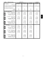
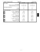
Page 44: ...2120 2 7 80 2 6 575 3 60 518 633 3 8 37 190 0 5 DD STD 980 4 2 84 4 0 MED 1000 2 0 71 1 9 HIGH 2120 2 1 80 2 0 TABLE 39 581J 05A 1 STAGE COOLING 4 TONS V Ph Hz VOLTAGE COMP ea OFM ea IFM RANGE RLA LRA WATTS FLA TYPE Max WATTS Max AMP Draw EFF at Full Load FLA MIN MAX 208 1 60 187 253 21 8 117 325 1 4 DD STD 980 7 8 84 7 4 230 1 60 187 253 21 8 117 325 1 4 DD STD 980 7 8 84 7 4 208 3 60 187 253 13 ...

Page 45: ...7 0 52 325 0 9 DD STD 980 4 2 84 4 0 MED 2120 2 7 80 2 6 HIGH 2615 3 6 81 3 4 575 3 60 518 633 5 1 40 325 0 9 DD STD 980 4 2 84 4 0 MED 1390 2 1 81 2 0 HIGH 3775 2 9 81 2 8 TABLE 41 581J 07A 1 STAGE COOLING 6 TONS V Ph Hz VOLTAGE COMP ea OFM ea IFM RANGE RLA LRA WATTS FLA TYPE Max WATTS Max AMP Draw EFF at Full Load FLA MIN MAX 208 3 60 187 253 19 0 123 325 1 5 STD 2120 5 5 80 5 2 MED 2615 7 9 81 ...

Page 46: ... 4 81 7 4 575 3 60 518 633 4 2 33 4 2 33 325 0 6 STD 1379 2 5 80 2 4 MED 3775 2 9 81 2 8 HIGH 4400 5 9 81 5 6 TABLE 43 581J 09D 2 STAGE COOLING 8 5 TONS V Ph Hz VOLTAGE COMP Cir 1 COMP Cir 2 OFM ea IFM RANGE RLA LRA RLA LRA WATTS FLA TYPE Max WATTS Max AMP Draw EFF at Full Load FLA MIN MAX 208 3 60 187 253 13 7 83 13 7 83 325 1 5 STD 1448 5 46 80 5 2 MED 2120 5 46 80 5 2 HIGH 2694 10 5 80 10 0 230...

Page 47: ...9 2 15 9 51 05 208 230 1 60 DD STD 0 48 1 9 36 1 50 35 127 38 0 50 37 129 208 230 3 60 DD STD 0 48 1 9 25 9 30 26 93 27 8 40 28 95 MED 23 4 30 23 98 25 3 30 25 100 HIGH 23 7 30 23 116 25 6 30 26 118 460 3 60 DD STD 0 25 1 0 12 7 15 13 47 13 7 20 14 48 MED 10 8 15 11 49 11 8 15 12 50 HIGH 11 3 15 11 58 12 3 15 12 59 575 3 60 DD STD 0 24 1 9 10 9 15 11 43 12 8 15 13 45 MED 8 8 15 9 44 10 7 15 11 46 ...

Page 48: ... 10 9 15 11 53 05 208 230 1 60 DD STD 0 48 1 9 40 9 60 41 132 42 8 60 43 134 208 230 3 60 DD STD 0 48 1 9 30 7 40 31 98 32 6 45 34 100 MED 28 2 40 29 103 30 1 40 31 105 HIGH 28 5 40 29 121 30 4 40 31 123 460 3 60 DD STD 0 25 1 0 14 9 20 15 49 15 9 20 16 50 MED 13 0 15 13 51 14 0 20 14 52 HIGH 13 5 20 14 60 14 5 20 15 61 575 3 60 DD STD 0 24 1 9 12 6 15 13 45 14 5 20 15 47 MED 10 5 15 11 46 12 4 15...

Page 49: ... 80 HIGH 16 1 20 16 90 19 9 25 21 94 08 2 stage cool 208 230 3 60 STD 0 48 3 8 38 8 50 41 191 42 6 50 45 195 MED 38 8 50 41 202 42 6 50 45 206 HIGH 43 6 50 46 245 47 4 60 51 249 460 3 60 STD 0 25 1 8 17 9 20 19 95 19 7 25 21 97 MED 17 9 20 19 101 19 7 25 21 103 HIGH 19 7 25 21 123 21 5 25 23 125 575 3 60 STD 0 24 3 8 13 1 15 14 77 16 9 20 18 81 MED 12 7 15 13 81 16 5 20 18 85 HIGH 13 5 15 14 92 17...

Page 50: ...19 82 HIGH 17 8 25 18 92 21 6 25 23 96 08 2 stage cool 208 230 3 60 STD 0 48 3 8 43 6 50 46 196 47 4 60 51 200 MED 43 6 50 46 207 47 4 60 51 211 HIGH 48 4 60 52 250 52 2 60 56 254 460 3 60 STD 0 25 1 8 20 1 25 21 97 21 9 25 23 99 MED 20 1 25 21 103 21 9 25 23 105 HIGH 21 9 25 23 125 23 7 30 26 127 575 3 60 STD 0 24 3 8 14 8 20 16 79 18 6 20 20 83 MED 14 4 20 15 83 18 2 20 20 87 HIGH 15 2 20 16 94 ...

Page 51: ...51 TYPICAL WIRING DIAGRAMS C08518 Fig 15 1 Stage Cooling Typical Power Diagram 581J ...

Page 52: ...52 TYPICAL WIRING DIAGRAMS cont C08577 Fig 16 2 Stage Cooling Typical Power Diagram 581J ...

Page 53: ...53 C08524 Fig 17 1 Stage Typical Wiring Diagram 581J ...

Page 54: ...54 C08578 Fig 18 2 Stage Typical Wiring Diagram 581J ...

Page 55: ...itiates power to the second stage of the main gas valve When the thermostat is satisfied W1 and W2 open and the gas valve closes interrupting the flow of gas to the main burners If the call for W1 lasted less than 1 minute the heating cycle will not terminate until 1 minute after W1 became active If the unit is controlled through a room thermostat set for fan auto the indoor fan motor will continu...

Page 56: ...control will modulate the dampers open to maintain the mixed air temperature setpoint at 50_F 10_C to 55_F 13_C If there is a further demand for cooling cooling second stage Y2 is energized then the control will bring on compressor stage 1 to maintain the mixed air temperature setpoint The EconoMi er IV damper will be open at maximum position EconoMi er IV operation is limited to a single compress...

Page 57: ... 09 13 23 A Thermostats 1 Thermostat must a energize both W and G when calling for heat b have capability to energize 2 different stages of cooling and 2 different stages of heating c include capability for occupancy scheduling 23 09 23 Direct digital Control system for HVAC 23 09 23 13 Decentralized Rooftop Units 23 09 23 13 A NA 1 Shall be ASHRAE 62 2001 compliant 2 Shall accept 18 32 VAC input ...

Page 58: ...urge protection circuitry through solid state polyswitches Polyswitches shall be used on in coming power and network connections Polyswitches will return to normal when the trip condition clears 11 Shall have a battery back up capable of a minimum of 10 000 hours of data and time clock retention during power outages 12 Shall have built in support for Bryant technician tool 13 Shall include an EIA ...

Page 59: ...top unit Contained within the unit enclosure shall be all factory wiring piping controls and special features required prior to field start up 3 Unit shall use environmentally sound PuronR refrigerant 4 Unit shall be installed in accordance with the manufacturer s instructions 5 Unit must be selected and installed in compliance with local state and federal codes 23 81 19 13 B Quality Assurance 1 U...

Page 60: ...to AHRI Standards 210 240 or 340 360 minimum exterior sweat criteria Interior surfaces shall be insulated with a minimum 1 2 in thick 1 lb density flexible fiberglass insulation neoprene coated on the air side Aluminum foil faced fiberglass insulation shall be used in the gas heat compartment 4 Base of unit shall have a minimum of four locations for thru the base gas and electrical connections fac...

Page 61: ...ade using an LED 3 Standard Heat Exchanger construction a Heat exchanger shall be of the tubular section type constructed of a minimum of 20 gauge steel coated with a nominal 1 2 mil aluminum silicone alloy for corrosion resistance b Burners shall be of the in shot type constructed of aluminum coated steel c Burners shall incorporate orifices for rated heat output up to 2000 ft 610m elevation Addi...

Page 62: ...Impact resistance shall be up to 160 in lb ASTM D2794 93 g Humidity and water immersion resistance shall be up to minimum 1000 and 250 hours respectively ASTM D2247 92 and ASTM D870 92 h Corrosion durability shall be confirmed through testing to be no less than 1000 hours salt spray per ASTM B117 90 5 Optional E coated aluminum fin aluminum tube condenser coils a Shall have a flexible epoxy polyme...

Page 63: ...afety factors above that rating shall be required 2 Electric Drive Direct Drive X13 5 Speed Torque Evaporator Fan a Multi speed motor with easy quick adjustment settings b Blower fan shall be double inlet type with forward curved blades c Shall be constructed from steel with a corrosion resistant finish and dynamically balanced d Standard on all 04 06 models with 208 230 1 60 operation e Standard ...

Page 64: ...all be a Two Position Damper Damper travel shall be from the full closed position to the field ad justable open setpoint b Damper shall include adjustable damper travel from 25 to 100 full open c Damper shall include single or dual blade gear driven dampers and actuator motor d Actuator shall be direct coupled to damper gear No linkage arms or control rods shall be acceptable e Damper will admit u...

Page 65: ...r horizontal return configurations shall be available c Horizontal power exhaust is shall be mounted in return ductwork d Power exhaust shall be controlled by economizer controller operation Exhaust fans shall be energized when dampers open past the 0 100 adjustable setpoint on the economizer control 13 Roof Curbs Vertical a Full perimeter roof curb with exhaust capability providing separate air s...

Page 66: ...ual detector modules 5 Can be wired to up to 14 other duct smoke detectors for multiple fan shutdown applications 19 Winter start kit a Shall contain a bypass device around the low pressure switch b Shall be required when mechanical cooling is required down to 25_F 4_C c Shall not be required to operate on an economizer when below an outdoor ambient of 40_F 4_C 20 Time Guard a Shall prevent compre...

Reviews: