65
a. Powered convenience outlet.
(1.) Outlet shall be powered from main line power to the rooftop unit.
(2.) Outlet shall be powered from line side or load side of disconnect by installing contractor, as required by
code. If outlet is powered from load side of disconnect, unit electrical ratings shall be UL certified and
rated for additional outlet amperage.
(3.) Outlet shall be factory--installed and internally mounted with easily accessible 115--v female receptacle.
(4.) Outlet shall include 15 amp GFI receptacles with independent fuse protection.
(5.) Voltage required to operate convenience outlet shall be provided by a factory--installed step--down trans-
former.
(6.) Outlet shall be accessible from outside the unit.
(7.) Outlet shall include a field--installed “Wet in Use” cover.
b. Non--Powered convenience outlet.
(1.) Outlet shall be powered from a separate 115/120v power source.
(2.) A transformer shall not be included.
(3.) Outlet shall be factory--installed and internally mounted with easily accessible 115--v female receptacle.
(4.) Outlet shall include 15 amp GFI receptacles with independent fuse protection.
(5.) Outlet shall be accessible from outside the unit.
(6.) Outlet shall include a field--installed “Wet in Use” cover.
10. Flue Discharge Deflector:
a. Flue discharge deflector shall direct unit exhaust vertically instead of horizontally.
b. Deflector shall be defined as a “natural draft” device by the National Fuel and Gas (NFG) code.
11. Thru--the--Base Connectors:
a. Kits shall provide connectors to permit gas and electrical connections to be brought to the unit through the
unit basepan.
b. Minimum of four connection locations per unit.
12. Propeller Power Exhaust:
a. Power exhaust shall be used in conjunction with an integrated economizer.
b. Independent modules for vertical or horizontal return configurations shall be available.
c. Horizontal power exhaust is shall be mounted in return ductwork.
d. Power exhaust shall be controlled by economizer controller operation. Exhaust fans shall be energized when
dampers open past the 0--100% adjustable setpoint on the economizer control.
13. Roof Curbs (Vertical):
a. Full perimeter roof curb with exhaust capability providing separate air streams for energy recovery from the
exhaust air without supply air contamination.
b. Formed galvanized steel with wood nailer strip and shall be capable of supporting entire unit weight.
c. Permits installation and securing of ductwork to curb prior to mounting unit on the curb.
14. High Altitude Gas Conversion Kit:
a. Package shall contain all the necessary hardware and instructions to convert a standard natural gas unit to op-
erate from 2000--7000 ft (610 to 2134m) elevation with natural gas or from 0--7000 ft (90--2134m) elevation
with liquefied propane.
15. Outdoor Air Enthalpy Sensor:
a. The outdoor air enthalpy sensor shall be used to provide single enthalpy control. When used in conjunction
with a return air enthalpy sensor, the unit will provide differential enthalpy control. The sensor allows the unit
to determine if outside air is suitable for free cooling.
16. Return Air Enthalpy Sensor:
a. The return air enthalpy sensor shall be used in conjunction with an outdoor air enthalpy sensor to provide dif-
ferential enthalpy control.
17. Indoor Air Quality (CO
2
) Sensor:
a. Shall be able to provide demand ventilation indoor air quality (IAQ) control.
b. The IAQ sensor shall be available in duct mount, wall mount, or wall mount with LED display. The setpoint
shall have adjustment capability.
18. Smoke detectors (factory--installed only):
a. Shall be a Four--Wire Controller and Detector.
b. Shall be environmental compensated with differential sensing for reliable, stable, and drift--free sensitivity.
c. Shall use magnet--activated test/reset sensor switches.
581J
Summary of Contents for 581J
Page 51: ...51 TYPICAL WIRING DIAGRAMS C08518 Fig 15 1 Stage Cooling Typical Power Diagram 581J ...
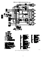
Page 52: ...52 TYPICAL WIRING DIAGRAMS cont C08577 Fig 16 2 Stage Cooling Typical Power Diagram 581J ...
Page 53: ...53 C08524 Fig 17 1 Stage Typical Wiring Diagram 581J ...
Page 54: ...54 C08578 Fig 18 2 Stage Typical Wiring Diagram 581J ...


