background image

800SA/801SA: Installation, Start–Up, Operating and Service and Maintenance Instructions

Manufacturer reserves the right to change, at any time, specifications and designs without notice and without obligations.

33

11. Verify  that  blower  wheel  is  centered  in  blower  housing  and  set

screw contacts the flat portion of the motor shaft. Loosen set screw

on blower wheel and reposition if necessary.

12. Spin the blower wheel by hand to verify that the wheel does not rub

on the housing.

13. Reinstall blower assembly in furnace.
14. Reinstall two screws securing blower assembly to blower deck.

15. Refer to  furnace


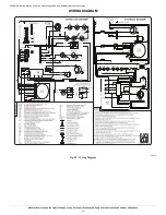
wiring  diagram, and  connect  thermostat leads if

previously


disconnected.

16. To check blower for proper rotation:

a. Turn on electrical supply.

b. Manually close blower access door switch.

NOTE: 

If thermostat terminals are jumpered at the time blower


access

door  switch  is  closed,  blower  will  run  for  90  sec  before


beginning  a

heating or cooling cycle.

c. Perform component self-test as shown at the bottom of the


SERVICE label, located on the front of blower access door.

d. Verify blower is rotating in the correct direction.

17. If  furnace  is  operating  properly,  RELEASE  BLOWER ACCESS

DOOR  SWITCH.  Remove  any  jumpers  or  reconnect


any

disconnected thermostat leads. Replace blower access


door.

18. Downflow  or  horizontal furnaces  with  vent pipe  through


furnace

only:

a. Install and connect short piece of vent pipe inside furnace


to 

existing vent.

b. Connect vent connector to vent elbow.

19. Reinstall outer door.
20. Cycle  furnace  through  one  complete


heating  and  cooling  cycle.

Verify  the  furnace  temperature  rise


as  shown  in  “Adjustments”

Section.  Adjust  temperature  rise  as


shown  in  “Adjustments”

Section.  If  outdoor  temperature  is


below  70°F,  (21°C)  turn  off

circuit breaker to outdoor unit before


running furnace in the cooling

cycle.  Turn  outdoor  circuit


breaker  on  after  completing  cooling

cycle.


CLEANING HEAT EXCHANGER 

The following steps should be performed by a qualified service agency:

NOTE: 

If  the  heat  exchangers  get  a  heavy  accumulation  of  soot  and

carbon,  they  should  be  replaced  rather  than  trying  to  clean  them

thoroughly.  A  heavy  build-up  of  soot  and  carbon  indicates  that  a

problem exists which needs to be corrected, such as improper adjustment

of  manifold  pressure,  insufficient  or  poor  quality  combustion  air,

incorrect  size  or  damaged  manifold  orifice(s),  improper  gas,  or  a

restricted heat exchanger. Action must be taken to correct the problem. 

If it becomes necessary to clean the heat exchangers because of dust or

corrosion, proceed as follows:

1. Turn OFF gas and electrical power to furnace.
2. Remove outer access door.
3. Disconnect vent connector from furnace vent elbow.
4.  For downflow or horizontal furnace having an internal vent pipe,

remove internal vent pipe within the casing. 

5. Disconnect wires to the following components. Mark wires to aid in

reconnection  of  (be  careful  when  disconnecting  wires  from

switches because damage may occur):

a. Draft safeguard switch.

b. Inducer motor.

c. Pressure switch(es).

d. Limit over-temperature switch.

e. Gas valve.

f. Hot surface igniter.

g. Flame-sensing electrode.

h. Flame rollout switches. 

6. Remove screws that fasten the collector box assembly to the cell

panel. Be careful not to damage the collector box. Inducer assembly

and elbow need not be removed from collector box.

7. Disconnect gas line from gas manifold.
8. Remove  the  5  screws  that  attach the  burner  assembly  to  the  cell

panel. The gas valve and individual burners need not be removed

from support assembly. Remove NOx baffles if installed.

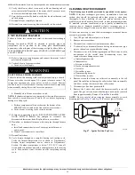
NOTE: 

Be  very  careful  when  removing  burner  assembly  to  avoid

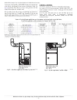
breaking igniter. See 

Fig. 47

 and 

Fig. 48

 for correct igniter location.

A05026

Fig. 47 – Igniter Position-Top View

CAUTION

!

UNIT DAMAGE HAZARD

Failure to follow this caution may result in shortened heat exchanger

life. 

Heating  fan  speed(s)  MUST  be  adjusted  to  provide  proper  air

temperature  rise  as  specified  on  the  rating  plate.  Recommended

operation is at the midpoint of the rise range or slightly above. Refer to

“SET TEMPERATURE RISE” under START-UP, ADJUSTMENT, and

SAFETY CHECK.

WARNING

!

ELECTRICAL SHOCK HAZARD

Failure to follow this warning could result in personal injury, or death. 

Blower access door switch opens 115-v power to furnace control. No

component  operation  can  occur  unless  switch  is  closed.  Exercise

caution to avoid electrical shock from exposed electrical components

when manually closing this switch for service purposes.

1-7/8

(47.6 mm)

Summary of Contents for 800SA

Page 1: ...r Hour 21 EXTERIOR MASONRY CHIMNEY FAN NAT INSTALLATIONS WITH TYPE B DOUBLE WALL VENT CONNECTORS NFPA AGA 22 VENTING NOTES FOR Fig 31 Fig 43 25 START UP ADJUSTMENT AND SAFETY CHECK 25 GENERAL 25 Table...

Page 2: ...residential garage must be installed as specified in the warning box in the Location section 9 The furnace may be used for construction heat provided that the furnace installation and operation compli...

Page 3: ...tion in a Garage CODES AND STANDARDS Follow all national and local codes and standards in addition to these instructions The installation must comply with regulations of the serving gas supplier local...

Page 4: ...tic discharge can affect electronic components Follow the Electrostatic Discharge Precautions Procedure listed below during furnace installation and servicing to protect the furnace electronic control...

Page 5: ...a volume of at least 50 cubic feet per 1 000 Btuh input rating for all gas appliances installed in the space Spaces having less than 50 cubic feet per 1 000 Btuh require the OUTDOOR COMBUSTION AIR MET...

Page 6: ...ns from the current edition of National Fuel Gas Code ANSI Z223 1 NFPA 54 1 For other than fan assisted appliances such as a draft hood equipped water heater A04002 1 SQ IN PER 4000 BTUH DUCTS TO OUTD...

Page 7: ...and dilution of flue gases However in buildings with unusually tight construction additional air MUST be provided using the methods described in the Outdoor Combustion Air Method section 4 Unusually...

Page 8: ...Table 3 and Fig 9 3 Construct plenum to dimensions specified see Table 3 and Fig 9 4 If downflow subbase KGASB is used install as shown see Table 10 If Coil Assembly Part No CNPV CNRV CAP and CNR or...

Page 9: ...red 11 13 16 284 19 483 13 7 16 341 20 5 8 600 Downflow Applications on Combustible Flooring with Cased Coil subbase not required 12 5 16 319 19 483 13 5 16 338 20 508 17 1 2 445 Upflow Applications o...

Page 10: ...revent screws from pulling out use 2 8 x 3 4 in 19 mm screws into the side and 2 8 x 3 4 in 19 mm screws in the bottom of the furnace casing for each strap see Fig 14 and Fig 15 If the screws are atta...

Page 11: ...0 ft 3 M of main duct to the first branch take off may require internal acoustical lining As an alternative fibrous ductwork may be used if constructed and installed in accordance with the latest edit...

Page 12: ...915 915 825 785 740 700 48070E21 Gray Cooling Do not use for heating 1735 1685 1640 1595 1545 1495 1450 1405 1360 1310 Yellow Alt Cooling or alt Heating 1480 1435 1395 1340 1290 1240 1190 1135 1085 10...

Page 13: ...side inlets a combination of 1 side and the bottom or the bottom only will ensure adequate return air openings for airflow requirements above 1800 CFM Fig 17 Dimensional Drawing 60110E24 Gray Cooling...

Page 14: ...of Massachusetts 1 Gas supply connections MUST be performed by a licensed plumber or gas fitter 2 When flexible connectors are used the maximum length shall not exceed 36 inches 915 mm 3 When lever h...

Page 15: ...NPT plugged tapping accessible for test gauge connection MUST be installed immediately upstream of gas supply connection to furnace and downstream of manual equipment shutoff valve WARNING FIRE OR EXP...

Page 16: ...electrical circuit with a properly sized fuse or circuit breaker for this furnace See Table 7 for wire size and fuse specifications A readily accessible means of electrical disconnect must be located...

Page 17: ...WITCH WHT BLK WHT BLK NOTES Connect Y terminal in furnace as shown for proper blower operation Some thermostats require a C terminal connection as shown If any of the original wire as supplied must be...

Page 18: ...es into electrical box 9 Remove cover from furnace J Box 10 Route field ground wire through holes in electrical box and casing and into furnace J Box 11 Reattach furnace J Box to furnace casing with s...

Page 19: ...board thermostat strip The HUM terminal is energized when the pressure switch closes during a call for heat see Fig 28 NOTE DO NOT connect furnace control HUM terminal to HUM humidifier terminal on Th...

Page 20: ...or condensation in the venting system These furnaces are approved for common venting and multistory venting with other fan assisted or draft hood equipped appliances in accordance with the NFGC the lo...

Page 21: ...appliances connected to the venting system are not in operation 1 Seal any unused openings in venting system 2 Inspect the venting system for proper size and horizontal pitch as required in the curre...

Page 22: ...on in the furnace and or venting system Derating is permitted only for altitudes above 2000 ft 610 M 3 Adjust the air temperature rise to the midpoint of the rise range or slightly above Low air tempe...

Page 23: ...the furnace being vented Follow all manufacturer s installation requirements for venting and termination included with the listed mechanical venter Caution For the following applications use the mini...

Page 24: ...lication Vent Elbow Left A03208 Fig 36 Upflow Application Vent Elbow Up A03212 Fig 37 Downflow Application Vent Elbow Up then Right A03218 Fig 38 Horizontal Right Application Vent Elbow Right SEE NOTE...

Page 25: ...Data Sheet for accessory listing 6 Factory authorized accessory Downflow Vent Guard Kit required in downflow installations with lower vent configuration See Product Data Sheet for accessory listing 7...

Page 26: ...ure will not operate if any thermostat signal is present at the control 4 Component test sequence is as follows see service label attached to furnace or Fig 44 a LED will display previous status code...

Page 27: ...fices See EXAMPLE 1 3 Adjust manifold pressure to obtain correct input rate a Turn gas valve ON OFF switch to OFF b Remove manifold pressure tap plug from gas valve see Fig 21 c Connect a water column...

Page 28: ...When thermometer readings stabilize subtract return air temperature from supply air temperature to determine air temperature rise NOTE If the temperature rise is outside this range first check 1 Gas i...

Page 29: ...Ammeter WARNING FURNACE OVERHEATING HAZARD Failure to follow this caution may result in reduced furnace life Recheck temperature rise It must be within limits specified on the rating plate Recommende...

Page 30: ...urn thermostat below room temperature or from HEAT to OFF and turn 115v power OFF then back ON 3 Check Pressure Switch This control proves operation of the draft inducer blower a Turn off 115 v power...

Page 31: ...S switch until LED goes out then reconnect it NOTE If wire to LS or DSS is disconnected longer than 4 sec main blower starts and status code is overwritten with a limit circuit 33 code 2 When above it...

Page 32: ...wheel as follows 1 Turn off electrical supply to furnace 2 Remove outer door 3 For downflow or horizontal furnaces having vent pipes within the furnace that pass in front of the blower access door a...

Page 33: ...eavy build up of soot and carbon indicates that a problem exists which needs to be corrected such as improper adjustment of manifold pressure insufficient or poor quality combustion air incorrect size...

Page 34: ...TV sealant G E 162 P771 9003 is available through RCD in 3 oz tubes 12 Apply new sealant to flange of collector box and attach to cell panel using existing screws making sure all screws are secure 13...

Page 35: ...zing the humidifier terminal HUM The inducer motor IDM will remain energized for a 5 second post purge period The blower motor BLWM and air cleaner terminal EAC 1 will remain energized for 90 120 150...

Page 36: ...tart Up Operating and Service and Maintenance Instructions Manufacturer reserves the right to change at any time specifications and designs without notice and without obligations 36 WIRING DIAGRAM A19...

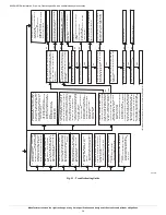
Page 37: ...f s u o i v e r p o n s a w r a t s l l i w r e c u d n i e h T e c n e u q e s t s e t t n e n o p m o c f e i r b a h g u o r h t o g l l i w n u r d n a t w o l b I S H e h T t s e t t n e n o p m...

Page 38: ...estricted duct system Loose blower wheel Defective switch or connections Defective blower motor or capacitor Inadequate combustion air supply flame rollout switch open Restricted vent Proper vent sizi...

Page 39: ...ealer listing by brand name or contact BRYANT HEATING COOLING SYSTEMS Consumer Relations Department P O Box 4952 Syracuse New York 13221 4952 1 800 428 4326 Have available the model number series numb...

Page 40: ...46231 Edition Date 03 20 Catalog No II800SA 04 Replaces II800SA 03 800SA 801SA Installation Start Up Operating and Service and Maintenance Instructions Manufacturer reserves the right to change at any...

Reviews: