background image

73

SERVICE AND MAINTENANCE

PROCEDURES

Untrained personnel can perform basic maintenance functions such

as cleaning and replacing air filters. All other operations must be

performed by trained service personnel. A qualified service person
should inspect the furnace once a year.

FIRE, INJURY OR DEATH HAZARD

Failure to follow this warning could result in personal

injury, death and/or property damage.
The ability to properly perform maintenance on this

equipment requires certain knowledge, mechanical skills,

tools, and equipment. If you do not possess these, do not

attempt to perform any service and maintenance on this

equipment other than those procedures recommended in the

Owner’s Manual.

!

WARNING

ENVIRONMENTAL HAZARD

Failure to follow this caution may result in environmental

pollution.
Remove and recycle all components or materials (i.e. oil,

refrigerant, control board, etc.) before unit final disposal.

CAUTION

!

ELECTRICAL SHOCK, FIRE OR EXPLOSION

HAZARD

Failure to follow this warning could result in personal

injury or death, or property damage.
Before installing, modifying, or servicing system, main

electrical disconnect switch must be in the OFF position and

install a lockout tag.

There may be more than one

disconnect switch. Lock out and tag switch with a suitable

warning label. Verify proper operation after servicing.

Always reinstall access doors after completing service and

maintenance.

!

WARNING

ELECTRICAL OPERATION HAZARD

Failure to follow this caution may result in improper

furnace operation or failure of furnace.
Label all wires prior to disconnection when servicing

controls. Wiring errors can cause improper and dangerous

operation.

CAUTION

!

General

These instructions are written as if the furnace is installed in an
upflow application. An upflow furnace application is where the

blower is located below the combustion and controls section of the

furnace, and conditioned air is discharged upward. Since this
furnace can be installed in any of the 4 positions shown in Fig. 2,

you must revise your orientation to component location
accordingly.

Electrical Controls and Wiring

Each pressure switch is labeled with the reference location (noted

as “COLLECTOR BOX--LPS” or “HOUSING--HPS” on the
switch). The nominal break point of each switch is shown on the

label below the reference location in inches of water column,
“W.C.” The maximum and minimum break point of the switch is

+/-- 0.05 inches of water column from the nominal break point of
the switch. The maximum make point of the switch is 0.10 inches

of water above the maximum break point of the switch.

Example

: Nominal break point on pressure switch is 0.68--in.

W.C. The minimum break point of the switch is 0.63--in. W.C.

The maximum break point of the switch is 0.73--in. W.C. The
maximum make point of the switch is 0.83--in. W.C.

ELECTRICAL SHOCK HAZARD

Failure to follow this warning could result in personal injury

or death.
There may be more than one electrical supply to the furnace.

Check accessories and cooling unit for additional electrical

supplies that must be shut off during furnace servicing. Lock

out and tag switch with a suitable warning label.

!

WARNING

The electrical ground and polarity for 115--v wiring must be
properly maintained. Refer to Fig. 37 for field wiring information

and to Fig. 72 for furnace wiring information.

NOTE

: If the polarity is not correct, the STATUS LED on the

control will flash rapidly and prevent the furnace from heating. The
control system also requires an earth ground for proper operation
of the control and flame--sensing electrode.
The 24--v circuit contains an automotive--type, 3--amp. fuse located
on the control. See Fig. 38. Any shorts of the 24--v wiring during

installation, service, or maintenance will cause this fuse to blow. If

fuse replacement is required, use ONLY a 3--amp. fuse. The control
LED will display status code 24 when fuse needs to be replaced.

Troubleshooting

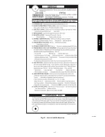
Refer to the service label. See Fig. 63.
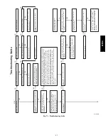
The Troubleshooting Guide can be a useful tool in isolating
furnace operation problems. Beginning with the word “Start,”

answer each question and follow the appropriate arrow to the next
item. See Fig. 71
The Guide will help to identify the problem or failed component.
After replacing any component, verify correct operation sequence.
Proper instrumentation is required to service electrical controls.

The control in this furnace is equipped with a Status Code LED
(Light--Emitting Diode) to aid in installation, servicing, and

troubleshooting. Status codes can be viewed at the indicator in
blower door. The amber furnace control LED is either ON

continuously, rapid flashing, or a code composed of 2 digits. The

first digit is the number of short flashes, the second digit is the
number of long flashes.
For an explanation of status codes, refer to service label located on
control door or Fig. 63, and the troubleshooting guide which can

be obtained from your distributor.

Retrieving Stored Fault Codes

NOTE

: Fault codes cannot be retrieved if a thermostat signal

(24-v on W, Y, G, etc.) is present, or if any delays such as blower
off-delays are active.
The stored status codes will NOT be erased from the control
memory when 115- or 24-v power is interrupted. See the Service

Label (Fig. 63) for more information. The most recent fault code
may be retrieved as follows:

1. Leave 115-v power connected to furnace.
2. Observe the status LED through the blower door (the lower

door on upflow applications) indicator. Refer to the Service
Label (Fig. 63) to interpret the LED.

922SA

Summary of Contents for 922SA

Page 1: ...tory org Portions of the text and tables are reprinted from current edition of NFPA 54 ANSI Z223 1 with permission of National Fire Protection Association Quincy MA 02269 and American Gas Association...

Page 2: ...aust vent terminal for the horizontally vented gas fueled heating appliance or equipment The sign shall read in print size no less than one half 1 2 inch in size GAS VENT DIRECTLY BELOW KEEP CLEAR OF...

Page 3: ...operations must be performed by trained service personnel When working on heating equipment observe precautions in literature on tags and on labels attached to or shipped with furnace and other safety...

Page 4: ...ee Fig 3 The furnace should be sized to provide 100 percent of the design heating load requirement plus any margin that occurs because of furnace model size capacity increments None of the furnace mod...

Page 5: ...dy with static electricity for example DO NOT move or shuffle your feet do not touch ungrounded objects etc 4 If you touch ungrounded objects and recharge your body with static electricity firmly touc...

Page 6: ...6 361 12 1 2 319 12 9 16 322 7 1 8 181 112 0 50 8 36060 122 5 55 6 36040 17 1 2 445 15 7 8 403 16 406 8 3 4 222 122 0 55 3 42060 132 0 59 9 48080 142 0 64 4 60080 21 533 19 3 8 492 19 1 2 495 10 1 2 2...

Page 7: ...IS LOCATED TO THE LEFT OF THE BURNER SECTION AND CONDITIONED AIR IS DISCHARGED TO THE RIGHT A12181 Fig 2 Multipoise Orientations 60 80 27 C 16 C SUPPLY AIR SEE PRODUCT DATA FOR ACCESSORY CONDENSATE T...

Page 8: ...tion system Refer to Air Ducts section S be provided ample space for servicing and cleaning Always comply with minimum fire protection clearances shown in Table 2 or on the furnace clearance to combus...

Page 9: ...ent closet and the space is well isolated from the living space or garage In addition other gas appliances installed in the space with the furnace may require outside air for combustion Follow the gui...

Page 10: ...input of all other than fan assisted appliances in Btuh hr Ifan combined input of all fan assisted appliances in Btuh hr ACH air changes per hour ACH shall not exceed 0 60 The following requirements...

Page 11: ...ble 4 Minimum Space Volumes for 100 Combustion Ventilation and Dilution Air from Outdoors OTHER THAN FAN ASSISTED TOTAL 1 000 S BTUH GAS INPUT RATE FAN ASSISTED TOTAL 1 000 S BTUH GAS INPUT RATE ACH 3...

Page 12: ...10 and 11 A field supplied accessory Horizontal Installation Kit trap grommet is required for all direct vent horizontal installations only The kit contains a rubber casing grommet designed to seal b...

Page 13: ...ports of the collector box Connect relief tube to port on collector box Rotate elbow to desired position and tighten clamp to 15 lb in Slide tube in stand offs to adjust length Connect the new pressu...

Page 14: ...on Attach condensate trap with screw to collector box Slide relief tube in stand offs to adjust length Vent elbow shown in alternate orientation Tighten clamp on inlet to vent elbow 15 lb in Align tra...

Page 15: ...osition and torque clamp on inlet 15 lb in Slide relief tube in stand offs to adjust length Attach condensate trap with screw to collector box Align trap over middle and right hand port on collector b...

Page 16: ...piped together and b There is an air gap at the point where the two drain lines meet or c All condensate piping is at least 3 4 in PVC and there is a relief tee at the top of condensate drain piping...

Page 17: ...n trap grommet is ONLY REQUIRED FOR DIRECT VENT APPLICATIONS It is NOT required for applications using single pipe or ventilated combustion air venting NOTICE TIP FROM CONTRACTORS When installing the...

Page 18: ...e DIRECTION OF AIRFLOW Condensing Furnace Evaporator Coil Blower 3 4 PVC 1 2 3 4 1 2 CPVC or larger Positive pressure Pressure lower than areas with Negative pressure 3 4 PVC DIRECTION OF AIRFLOW 1 2...

Page 19: ...ing Furnace Evaporator Coil Blower 3 4 PVC 3 4 1 2 CPVC or larger Positive pressure Pressure lower than areas with Negative pressure 3 4 PVC DIRECTION OF AIRFLOW 3 4 3 4 3 4 3 4 Open standpipe Optiona...

Page 20: ...0128 Fig 18 Drain Trap Connection and Routing Appearance may vary INSTALLATION This furnace is certified to leak 2 or less of nominal air conditioning CFM delivered when pressurized to 1 in water colu...

Page 21: ...nd then install bolt with nut in hole Install flat washer if desired 3 Install another nut on other side of furnace base Install flat washer if desired 4 Adjust outside nut to provide desired height a...

Page 22: ...NLY the furnace supply outlet air duct flanges or air conditioning coil casing when used DO NOT cut main furnace casing side to attach supply air duct humidifier or other accessories All supply side a...

Page 23: ...2 in 5 cm 600 283 0 04 12 0 05 12 0 07 17 0 10 26 0 24 60 0 16 40 800 378 0 06 15 0 07 19 0 10 25 0 15 39 0 34 85 0 23 59 1000 472 0 07 18 0 10 27 0 13 34 0 21 52 0 32 81 1200 566 0 08 20 0 14 36 0 17...

Page 24: ...4 406 x 635 x 19 16 x 25 x 3 4 406 x 635 x 19 Washable 21 533 16 x 25 x 3 4 406 x 635 x 19 20 x 25 x 3 4 508 x 635 x 19 Washable 24 1 2 622 16 x 25 x 3 4 406 x 635 x 19 24 x 25 x 3 4 610 x 635 x 19 W...

Page 25: ...ce Filler plates Screw 14 3 16 in Furnace with Filler Plates Centered 14 3 16 in Furnace Filler plate Screws 14 3 16 in Furnace with Filler Plates Off Set to Right Media Cabinet Installation Option fo...

Page 26: ...2 419 19 5 8 498 Downflow applications on combustible flooring KGASB sub base required 15 1 8 384 19 483 16 3 4 425 20 5 8 600 Downflow Applications on Combustible Flooring with CNPV CNRV CAR or CAP C...

Page 27: ...CLOSURE Representative drawing only some models may vary in appearance A170123 Fig 22 Removing Bottom Closure Panel 2 Screws BOTTOM PLATE SCREWS 4 1 Lay furnace on the back or side 2 Remove the four 4...

Page 28: ...N 1 4 IN 6 MM TO 1 2 IN 13 MM MAX A11237 Fig 25 Furnace Pitch Requirements ANY COMBINATION OF 1 2 OR 3 PERMITTED A11036 Fig 26 Upflow Return Air Configurations and Restrictions A11037 Fig 27 Downflow...

Page 29: ...Installation 2 IN 51 mm COMBUSTION AIR PIPE SEE VENTING SECTION Install 12 x 22 204 x 559 mm sheet metal in front of and above the burner compartment area The sheet metal MUST extend above the furnac...

Page 30: ...ctions to furnace with code approved tape or duct sealer NOTE Flexible connections should be used between ductwork and furnace to prevent transmission of vibration Ductwork passing through uncondition...

Page 31: ...Yellow 1650 1590 1535 1475 1425 1370 1315 1260 1205 1145 Blue 1495 1430 1365 1310 1260 1200 1145 1085 1030 970 Orange 1420 1355 1290 1235 1175 1120 1060 1005 945 890 Red 3 1200 1120 1060 995 940 875 8...

Page 32: ...a new listed connector Do not use a connector which has previously served another gas appliance Black iron pipe shall be installed at the furnace gas control valve and extend a minimum of 2 in 51 mm...

Page 33: ...death or property damage Before servicing disconnect all electrical power to furnace When servicing controls label all wires prior to disconnection Reconnect wires correctly Verify proper operation af...

Page 34: ...electrical box Do not leave splice connections unprotected inside the furnace The J Box cover mounting bracket and screws are shipped in the loose parts bag included with the furnace See Fig 34 for J...

Page 35: ...this warning could result in dangerous operation personal injury death or property damage Do not drill into blower shelf of furnace to route control wiring Route any control or accessory wiring to the...

Page 36: ...0 1 127 104 9 6 12 9 14 28 8 5 15 60120 115 60 1 127 104 9 6 12 9 14 28 8 5 15 Permissible limits of the voltage range at which the unit operates satisfactorily Unit ampacity 125 percent of largest op...

Page 37: ...CT CONDENSING UNIT TWO WIRE FURNACE C O N T R O L R G COM W C R G Y GND GND FIELD 24 V WIRING FIELD 115 208 230 460 V WIRING FACTORY 24 V WIRING FACTORY 115 V WIRING 208 230 OR 460 V THREE PHASE 208 2...

Page 38: ...INALS HUMIDIFIER TERMINAL 24 VAC 0 5 AMP MAX 3 AMP FUSE LED OPERATION DIAGNOSTIC LIGHT SEC 1 BLOWER SPEED SELECTION TERMINALS BL 1 PR 1 COM HEAT COOL FAN SPARE2 SPARE1 Y1 DHUM BLOWER OFF DELAY 120 180...

Page 39: ...Furnace with Single Speed Heat Pump Single Stage Furnace with Two Speed Heat Pump THERMOSTAT THERMOSTAT THERMOSTAT THERMOSTAT D D D D See notes 2 5 7 10 14 and 15 See notes 1 2 4 6 7 9 10 12 14 and 15...

Page 40: ...to this standard In Canada the primer and cement must be of the same manufacturer as the vent system GVS 65 Primer Purple for Royal Pipe or IPEX System 636 PVC CPVC Primer Purple Violet for Flue Gas V...

Page 41: ...4 for single pipe or ventilated combustion air option A furnace shall not be connected to a chimney flue serving a separate appliance designed to burn solid fuel Other gas appliances with their own ve...

Page 42: ...stion air pipe to the outdoors is not required for a single pipe vent system A 12 in 304 mm long pipe with a 2 in 51 mm tight radius 90 degree elbow is required to be attached to the combustion air pi...

Page 43: ...in accordance with U S A Installations Section 9 3 of current edition of NFPA 54 ANSI Z223 1 Air for Combustion and Ventilation and applicable provisions of the local building codes Canadian Installa...

Page 44: ...gth of the venting system ADDITIONAL INFORMATION FOR POLYPROPYLENE VENTING SYSTEMS Polypropylene venting systems include flexible vent pipe These flexible vent pipes have a different equivalent vent l...

Page 45: ...pe may result in nuisance pressure switch tripping Install the Vent and Combustion Air Pipes With the furnace installed in the required position remove the desired knockouts from the casing It will be...

Page 46: ...ting socket 14 Wipe excess cement from joint A continuous bead of ce ment will be visible around perimeter of a properly made joint 15 Handle pipe joints carefully until cement sets 16 Horizontal port...

Page 47: ...en vents or pairs of vents as shown in Fig 53 and 54 and all clearance shown in Fig 51 and 52 RECOMMENDED SUPPORT FOR VENT TERMINATIONS It is recommended that rooftop vent terminations in excess of 36...

Page 48: ...required by code 2 See Table below for approved materials for use in the U S A 3 ULC S636 vent systems must be composed of pipe fittings cements and primers from the same supplier 4 Factory accessory...

Page 49: ...60 000 BTUH Uninsulated 3 8 in Insulation 1 2 in Insulation Uninsulated 3 8 in Insulation 1 2 in Insulation Pipe Dia mm 38 51 64 38 51 64 38 51 64 38 51 64 76 38 51 64 76 38 51 64 76 7 6 1 6 1 6 1 6 1...

Page 50: ...ped in the loose parts bag or available through Replacement Components required under 10 ft 3 M TEVL in all orientations Required for installations from 0 2000 0 to 610 M above sea level Failure to us...

Page 51: ...EVL 95 ft 29 M For 2 pipe from Table 16 Is TEVL less than MEVL YES Therefore 2 pipe MAY be used Example 2 A direct vent 60 000 BTUH furnace installed at 2100 ft 640M Venting system includes FOR EACH P...

Page 52: ...nd Adapter A13074 Fig 40 Vent Coupling and Adapter with Gaskets TABS ON THE INDUCER OUTLET RESTRICTOR SNAP INTO THE SLOTS AT THE OUTLET OF THE INDUCER FOR USAGE SEE MAXIMUM EQUIVALENT VENT LENGTH TABL...

Page 53: ...lbows where possible to ensure conden sate drainage Slope vent pipe back to the furnace at least per foot A14546 Fig 42 Near Furnace Vent Connections FURNACE PIPE DIAMETER TRANSITION IN VERTICAL SECTI...

Page 54: ...fitt located above the vent termination within a horizontal distance of 2 ft 61 cm from the centerline of the vent termination 6 ft 2 M Clearance to a ventilation exhaust including HRV ERV on either W...

Page 55: ...combustion air connection UPFLOW VERTICAL VENT A11310A Fig 45 Upflow Configurations Appearance may vary See Notes for Venting Options 1 2 3 4 5 6 7 5 Rotate vent elbow to required position DOWNFLOW L...

Page 56: ...T RIGHT VENT CONFIGURATION A11329A Fig 47 Horizontal Left Appearance may vary See Notes for Venting Options ALTERNATE COMBUSTION AIR CONNECTIONS HORIZONTAL RIGHT VERTICAL VENT CONFIGURATION A11337 Req...

Page 57: ...VENT PIPE FLUSH SHOWING COUPLING VENT PIPE FLUSH WITH ADAPTER VENT PIPE ADAPTER WITH GASKET INSTALLED ON FURNACE VENT PIPE IS CUT FLUSH WITH TOP OF ADAPTER PRIME AND CEMENT VENT PIPE TO ADAPTER ALLOW...

Page 58: ...n a minimum of two sides beneath the floor See Note 4 Manufacturer s Recommendation See Notes 3 8 M Clearance to each side of the centerline extended above or below vent terminal of the furnace to a d...

Page 59: ...open on a minimum of two sides beneath the floor See Note 4 Manufacturer s Recommendation See Notes 3 8 M Clearance to each side of the centerline extended above or below vent terminal of the furnace...

Page 60: ...is greater Side wall termination with 2 elbows preferred 12 in min 305 mm from overhang or roof Maintain 12 in 305mm minimum clearance above highest anticipated snow level or grade whichever is great...

Page 61: ...305 MM CLEARANCE ABOVE HIGHEST ANTICIPATED SNOW LEVEL OR GRADE WHICHEVER IS GREATER COMBUSTION AIR ELBOW PARALLEL TO WALL OVERHANG 12 IN 305 MM MIN GROUND LEVEL OR ANTICIPATED SNOW LEVEL EXHAUST CLEAR...

Page 62: ...ipe hangar Ventilated Combustion Air intake termination in crawl space Ventilated Combustion Air intake pipe CRAWL SPACE ATTIC highest level of insulation A10497 Fig 56 Vent Terminations for Ventilate...

Page 63: ...some models may vary in appearance TO CODE APPROVED DRAIN OR CONDENSATE PUMP Tee Dry Well Cap water tight and removable Tee Dry Well Cap water tight and removable Tee Dry Well Cap water tight and remo...

Page 64: ...ver blower operates HUM 24vac terminal is only energized when the gas valve is energized in heating Prime Condensate Trap with Water CARBON MONOXIDE POISONING HAZARD Failure to follow these warnings c...

Page 65: ...ifferent orifice Tables have been provided in the furnace installation instructions to match the required orifice to the manifold pressure to the heat content and specific gravity of the gas To do thi...

Page 66: ...cu ft to obtain input rate g If clocked rate does not match required input from Step 1 increase manifold pressure to increase input or decrease manifoldpressuretodecreaseinput Repeatsteps bthrough e u...

Page 67: ...tails FIRE HAZARD Failure to follow this warning could result in personal injury death and or property damage Reinstall manifold pressure tap plug in gas valve to prevent gas leak WARNING FURNACE OVER...

Page 68: ...ate Multiplier for U S A ALTITUDE PERCENT OF DERATE DERATE MULTIPLIER FACTOR FT M 0 2000 0 610 0 1 00 2001 3000 610 914 4 6 0 95 3001 4000 914 1219 6 8 0 93 4001 5000 1219 1524 8 10 0 91 5001 6000 152...

Page 69: ...69 338311 201 Rev D A11600 Fig 63 Service Label Information 922SA...

Page 70: ...23 157 313 783 66 54 109 273 24 150 300 750 68 53 106 265 25 144 288 720 70 51 103 257 26 138 277 692 72 50 100 250 27 133 267 667 74 48 97 243 28 129 257 643 76 47 95 237 29 124 248 621 78 46 92 231...

Page 71: ...3 7 43 3 8 42 3 2 850 44 3 8 43 3 5 43 3 6 43 3 7 875 44 3 6 44 3 7 43 3 4 43 3 5 4000 900 44 3 4 44 3 5 44 3 7 44 3 8 1219 925 44 3 2 44 3 4 44 3 5 44 3 6 950 44 3 1 44 3 2 44 3 3 44 3 4 750 42 3 3...

Page 72: ...2 3 2 725 44 3 8 43 3 4 43 3 5 43 3 6 750 44 3 5 44 3 7 44 3 8 43 3 4 8000 775 44 3 3 44 3 4 44 3 5 44 3 7 2438 800 44 3 1 44 3 2 44 3 3 44 3 4 825 44 2 9 44 3 0 44 3 1 44 3 2 625 42 3 4 42 3 5 42 3 6...

Page 73: ...inimum break point of the switch is 0 63 in W C The maximum break point of the switch is 0 73 in W C The maximum make point of the switch is 0 83 in W C ELECTRICAL SHOCK HAZARD Failure to follow this...

Page 74: ...or switch and re install blower door 6 Verify furnace shut down by lowering thermostat setting below room temperature 7 Verify that furnace restarts by raising thermostat setting above room temperatur...

Page 75: ...ng or servicing system main electrical disconnect switch must be in the OFF position and install a lockout tag There may be more than one disconnect switch Lock out and tag switch with a suitable warn...

Page 76: ...ing cooling cycle See Fig 38 NOTE If R W W1 thermostat terminals are jumpered at the time blower door switch is closed blower will run for 90 sec before beginning a heating cycle a Perform component s...

Page 77: ...tance across both igniter leads in connector b Cold reading should be between 40 ohms and 70 ohms 5 Remove igniter assembly a Using a 1 4 in driver remove the two screws securing the igniter mounting...

Page 78: ...g Heat Exchangers The following items must be performed by a qualified service technician Primary Heat Exchangers If the heat exchangers get an accumulation of light dirt or dust on the inside they ma...

Page 79: ...AGE HAZARD Failure to follow this caution may result in damage to the furnace and other property damage Do not use ethylene glycol automotive antifreeze coolant or equivalent Failure of plastic compon...

Page 80: ...ROMMET SCREW LOCATION BLOWER HSG ASSY BRACKET BRACKET ENGAGEMENT SEE DETAIL A CAPACITOR OR POWER CHOKE WHEN USED BRACKET SCREW GND BLOWER HSG ASSY MOTOR BLOWER WHEEL BLOWER CUTOFF BLOWER DETAIL A A115...

Page 81: ...ergized as long as the blower motor BLWM is energized f Blower Off Delay When the thermostat is satisfied the R to W circuit is opened de energizing thegas valveGV stopping gas flowto theburners andde...

Page 82: ...h again at the thermostat will shift the contin uous blower speed from HEAT to COOL Repeating the procedure will shift the continuous blower speed from COOL to FAN speed The selection can be changed a...

Page 83: ...fault or status code 11 1 short and 1 long flash if there was no previous fault After the control repeats the code 4 times the control will go through a brief component test sequence The inducer will...

Page 84: ...3 more times before lockout 14 occurs If flame signal is lost during the blower on delay period blower will come on for the selected blower off delay Check the following items first before proceeding...

Page 85: ...85 338311 201 Rev D A11601 Fig 72 Wiring Diagram 922SA...

Page 86: ...by brand name or contact BRYANT HEATING COOLING SYSTEMS Consumer Relations Department P O Box 4952 Syracuse New York 13221 4952 1 800 428 4326 Have available the model number series number and serial...

Reviews: