background image

44

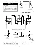
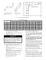
The trap can be constructed from a running tee of the same

diameter of the intake air pipe with

EITHER

a removable cap

attached to a 6-inch long pipe connected to the tee or the External

Vent Trap Kit to help prevent contaminants from entering the

furnace. See Fig. 43.
The External Vent Trap Kit accessory may be used as a trap for the

combustion air inlet pipe if a large amount of moisture must be

removed. The drain line may be connected to the same drain as the

furnace condensate and the evaporator coil condensate line

ONLY

if the inlet air trap drain and the evaporator coil drain empty into an

open segment of pipe above the drain. See Fig.18. When using

the External Vent Trap Kit, refer to those instructions for proper

drain connections.
The tee may also be connected to the intake air pipe on the side of

the casing. See Fig. 43.
In any configuration, it will be necessary to add the equivalent

length of the tee (15 feet/5 M) to the Total Equivalent Vent Length

of the venting system.

ADDITIONAL INFORMATION FOR

POLYPROPYLENE VENTING SYSTEMS

Polypropylene venting systems include flexible vent pipe.

These flexible vent pipes have a different equivalent vent

length than straight sections of PVC/ABS DWV vent pipe. Be

sure to make the appropriate deductions from the Maximum

Equivalent Vent Length (MEVL), or additions to the Total

Equivalent Vent Length (TEVL), when applying flexible vent

pipes

in

polypropylene

venting

systems.

See

the

polypropylene vent system manufacturer’s installation

instructions for details.
When using metric-sized venting systems, use these

equivalencies for obtaining the proper MEVL from the Tables:

Use 2” Vent Tables for 60 mm (o.d.) vent systems

Use 3” Vent Tables for 80 mm (o.d.) vent systems

Use 4” Vent Tables for 100 mm (o.d.) vent systems

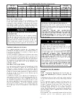
NOTICE

The measured length of pipe used in a single or 2--pipe termination

is included in the total vent length. Include deductions from the

Maximum Equivalent Vent Length (MEVL) contained in the

Venting Tables for elbows and flexible vent pipe.

Factory

accessory concentric vent terminations or pipe lengths and elbows

used for “standard” vent terminations (see vent termination figures

associated with Table 16) do not require a deduction from the

Maximum Equivalent Vent Length. Include a deduction for a Tee

when used for Alberta and Saskatchewan terminations.

NOTE

: Polypropylene venting systems MAY require additional

deductions from the MEVL, or additions to the TEVL, for vent

terminations and flexible pipe sections. See the polypropylene

venting system manufacturer’s instructions for details on

equivalent lengths of vent terminations and flexible vent pipes,

and for calculating total vent lengths.

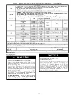
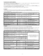
To calculate the Total Equivalent Vent Length (TEVL) of the

venting system:

1. Measure the individual distance from the furnace to the ter-

mination for each pipe.

2. Count the number of elbows for each pipe.

3. For each pipe, multiply the number of elbows by the equiv-

alent length for the type of elbow used. Record the equiva-

lent length of all the elbows for each pipe.

4. If a Tee is used on the termination (Alberta and

Saskatchewan, when required) record the equivalent length

of the Tee used.

5. Calculate Total Equivalent Vent Length by adding the

equivalent lengths of the fittings to the lengths of the indi-

vidual vent and combustion air pipes.

6. When using polypropylene venting systems with flexible

vent pipes, perform adjustments for the equivalent length of

the flexible vent pipe to the calculated total equivalent

venting system length. See the polypropylene vent system

manufacturer’s instructions for details.

7. Select a diameter of vent pipe from Table 16 and note the

Maximum Equivalent Vent Length (MEVL) shown for that

application for that specific furnace input size. Compare the

Total Equivalent Vent Length (TEVL) to the MEVL:

8. If the Total Equivalent Vent Length is

shorter

than the

Maximum Equivalent Vent Length for the diameter of pipe

chosen, then that diameter of pipe selected may be used.

9. If the Total Vent Length is

longer

than the Maximum

Equivalent Vent Length for the diameter of pipe chosen,

that diameter pipe MAY NOT be used for venting the fur-
nace. Try the next larger diameter pipe

.

NOTE

: If the calculated Total Equivalent Vent Lengths results in

different diameter pipes for the vent and combustion air, select the

larger diameter for both pipes.

NOTE

: If the Maximum Vent Length for diameter of the pipe

selected is longer than the measured length and the equivalent

length of all the fittings and terminations (TEVL), recalculate

Total Equivalent Vent Length using the next smaller diameter. If

the Maximum Equivalent Vent Length is still longer than the

longer TEVL of the vent pipe or combustion air pipe, then that

diameter of pipe selected may be used.

When installing vent systems pipe lengths of 10 ft. (3 M) or less,

use the smallest allowable pipe diameter. Using a pipe size greater

than required for short venting systems may result in loss of

efficiency, incomplete combustion, flame disturbance, or flame

sense lockout.

For vent systems longer than 10 ft. (3 M), any larger diameter vent

pipe shown in Table 16

FOR THAT SIZE FURNACE

may be

used.

Combustion Air and Vent Piping Insulation

Guidelines

NOTE

: Use closed cell, neoprene insulation or equivalent.

The vent pipe may pass through unconditioned areas. The amount

of exposed pipe allowed is shown in Table 15.

1. Using winter design temperature (used in load calculations),

find appropriate temperature for your application and fur-

nace model.

2. Determine the amount of total and exposed vent pipe.

3. Determine required insulation thickness for exposed pipe

length(s).

4. When combustion air inlet piping is installed above a sus-

pended ceiling, the pipe

MUST

be insulated with moisture

resistant insulation such as Armaflex or other equivalent

type of insulation.

5. Insulate combustion air inlet piping when run in warm, hu-

mid spaces.

6. Install the insulation per the insulation manufacturer’s in-

stallation instructions.

NOTE

: Pipe length (ft. / M) specified for maximum pipe lengths

located in unconditioned spaces cannot exceed total allowable pipe

length as calculated from Table 16.

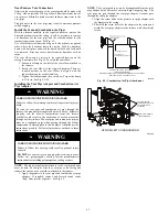
Configure the Furnace

CARBON MONOXIDE POISONING HAZARD

Failure to follow this warning could result in personal

injury or death.
To route the vent pipe and combustion air pipe through the

furnace, the manufacturer supplied kit must be used. Failure

to properly seal the blower compartment from the furnace

vestibule could result in the circulation of carbon monoxide

throughout the structure. The vent pipe and combustion air

pipe must be a continuous pipe while passing through the

blower compartment. Seals supplied in this kit must be

installed per the instructions provided. Follow all

procedures outlined in these instructions.

WARNING

!

Summary of Contents for 926TB

Page 1: ...g Dimensions 23 Air Delivery CFM 26 Maximum Capacity of Pipe 31 Electrical Data 35 Combustion Air Vent Pipe Fitting Cement Material 40 Vent Termination Kit for Direct Vent 2 Pipe Systems 41 Hangar Spa...

Page 2: ...exhaust vent terminal for the horizontally vented gas fueled heating appliance or equipment The sign shall read in print size no less than one half 1 2 inch in size GAS VENT DIRECTLY BELOW KEEP CLEAR...

Page 3: ...406 8 3 4 222 133 60 3 36060V14 14 3 16 361 12 1 2 319 12 9 16 322 7 1 8 181 132 59 9 42060V17 17 1 2 445 15 7 8 403 16 406 8 3 4 222 139 63 0 48080V17 17 1 2 445 15 7 8 403 16 406 8 3 4 222 147 66 7...

Page 4: ...er operations must be performed by trained service personnel When working on heating equipment observe precautions in literature on tags and on labels attached to or shipped with furnace and other saf...

Page 5: ...ce is factory shipped for use with natural gas The furnace can be converted in the field for use with propane gas when a factory supplied conversion kit is used Refer to the furnace rating plate for c...

Page 6: ...S The use of copper tubing for gas piping is not approved by the state of Massachusetts Electrical Connections S US Current edition of National Electrical Code NEC NFPA 70 S CANADA Current edition of...

Page 7: ...parts bag contents This furnace must S be installed so the electrical components are protected from water S not be installed directly on any combustible material other than wood flooring refer to SAF...

Page 8: ...must be installed in accordance with the current edition of NFPA 54 ANSI Z223 1 or CAN CSA B149 2 See Fig 4 WARNING 18 IN 457 2 mm MINIMUM TO BURNERS A93044 Fig 4 Installation in a Garage FIRE HAZARD...

Page 9: ...changers and shorten furnace life Air contaminants are found in aerosol sprays detergents bleaches cleaning solvents salts air fresheners and other household products CAUTION CARBON MONOXIDE POISONING...

Page 10: ...2 kW of the total input rating of all gas appliances in the space but not less than 100 in 2 0 06 m2 One opening shall commence within 12 in 300 mm of the ceiling and the second opening shall commence...

Page 11: ...s Table 4 Minimum Space Volumes for 100 Combustion Ventilation and Dilution Air from Outdoors OTHER THAN FAN ASSISTED TOTAL 1 000 S BTUH GAS INPUT RATE FAN ASSISTED TOTAL 1 000 S BTUH GAS INPUT RATE A...

Page 12: ...required for all direct vent horizontal installations only The kit contains a rubber casing grommet designed to seal between the furnace casing and the condensate trap See Fig 8 Remove knockout Insta...

Page 13: ...operation or damage to equipment If furnace environment has the potential of freezing the drain trap and drain line must be protected The use of accessory drain trap heaters electric heat tape and or...

Page 14: ...ow 4 From inside the casing insert the formed grommet end of the elbow through the 7 8 in knockout in the casing 5 Pull the grommet through the casing from the outside until it is seated in the knocko...

Page 15: ...m per meter of slope down and away from the furnace in horizontal sections of drain line The field supplied accessory horizontal drain trap grommet is ONLY REQUIRED FOR DIRECT VENT APPLICATIONS It is...

Page 16: ...ipe into the outlet stub on the drain tube 10 Connect additional condensate piping to a code approved drain or to a condensate pump approved for use with acidic furnace condensate and compatible with...

Page 17: ...se parts bag DIRECTION OF AIRFLOW A170135 Fig 18 Example of Field Drain Attachment INSTALLATION This furnace is certified to leak 2 or less of nominal air conditioning CFM delivered when pressurized t...

Page 18: ...not use side return air openings in DOWNFLOW configuration See Fig 22 23 and 24 Leveling Legs If Desired In upflow position with side return inlet s leveling legs may be used See Fig 20 Install field...

Page 19: ...th bottom closure panel installed in bottom return air opening Remove and discard this panel when bottom return air is used To remove bottom closure panel see Fig 27 and 28 Horizontal Installation NOT...

Page 20: ...all be accessible when the furnace is installed and shall be of such a size that the heat exchanger can be viewed for possible openings using light assistance or a probe can be inserted for sampling t...

Page 21: ...finished ceiling 2 IN 51 mm COMBUSTION AIR PIPE SEE VENTING SECTION Install 12 x 22 204 x 559 mm sheet metal in front of and above the burner compartment area The sheet metal MUST extend above the fur...

Page 22: ...the side of the furnace or side and bottom when a bottom plenum is used See Fig 22 and 30 For downflow applications the Media Cabinet or field supplied accessory air cleaner must only be connected to...

Page 23: ...berglass Pleated CFM L s 1 in 2 5 cm 4 in 10 cm 1 in 2 5 cm 2 in 5 cm 1 in 2 5 cm 2 in 5 cm 800 378 0 03 9 0 03 8 0 05 12 0 07 18 0 17 43 0 11 28 1000 472 0 04 11 0 05 12 0 06 16 0 09 24 0 22 55 0 15...

Page 24: ...URATIONS A12220 Fig 29 Sample Inlet Air Pipe Connection for Polypropylene Venting Systems 14 3 16 and 17 1 2 in Furnace 16 in Media Cabinet 21 in Furnace 4 Ton or less AC capacity airflow 20 in Media...

Page 25: ...ubbase not required 15 7 8 403 19 483 16 1 2 419 19 5 8 498 Downflow applications on combustible flooring subbase required 15 1 8 384 19 483 16 3 4 425 20 5 8 600 Downflow Applications on Combustible...

Page 26: ...Heating SW1 High Heat Airflow3 800 770 730 700 665 635 605 570 540 510 Low Heat Airflow3 560 520 470 425 390 See note 4 Unit Size 36040V17 Clg CF Switch settings External Static Pressure ESP Clg Switc...

Page 27: ...Airflow3 1115 1090 1060 1035 1010 980 955 930 905 875 Low Heat Airflow3 780 740 695 655 615 575 530 490 450 405 Unit Size 42060V17 Clg CF Switch settings External Static Pressure ESP Clg Switches SW2...

Page 28: ...See Note 4 Heating SW1 High Heat Airflow3 1470 1435 1400 1365 1330 1295 1260 1225 1190 1155 Low Heat Airflow3 1150 1110 1070 1030 990 950 910 870 830 790 Unit Size 60080V21 Clg CF Switch settings Ext...

Page 29: ...5 1080 1020 940 890 825 785 710 660 590 Heating SW1 High Heat Airflow3 1905 1865 1825 1775 1730 1685 1640 1590 1545 1490 Low Heat Airflow3 1480 1435 1375 1330 1265 1215 1160 1115 1060 1005 Unit Size 6...

Page 30: ...s to furnace with code approved tape or duct sealer NOTE Flexible connections should be used between ductwork and furnace to prevent transmission of vibration Ductwork passing through unconditioned sp...

Page 31: ...p externally in the riser leading to furnace as shown in Fig 32 Connect a capped nipple into lower end of tee Capped nipple should extend below level of furnace gas controls Place a ground joint union...

Page 32: ...d result in personal injury or death Blower door switch opens 115 v power to control No component operation can occur Do not bypass or close switch with blower door removed WARNING See Fig 39 for fiel...

Page 33: ...Electrical Box on Furnace Casing Use a separate fused branch electrical circuit with a properly sized fuse or circuit breaker for this furnace See Table 11 for wire size and fuse specifications A read...

Page 34: ...e field power wiring into external electrical box 5 Pull furnace line voltage power wires through strain relief bushing of the external electrical box 6 Pull the ground wire of the field line voltage...

Page 35: ...together using a factory accessory twinning kit See Fig 40 Alternate Power Supplies This furnace is designed to operate on utility generated power which has a smooth sinusoidal waveform If the furnac...

Page 36: ...36 W W1 W2 COM Y Y2 R G A11401 Fig 39 Typical Two Stage Field Wiring Diagram A190044 Fig 40 Example of Variable Speed Furnace Control...

Page 37: ...Stage Furnace with Single Speed Heat Pump Modulating and 2 Stage Furnace with Two Speed Heat Pump See notes 2 5 7 10 11 16 and 17 See notes 1 2 4 6 7 9 10 11 15 16 and 17 THERMOSTAT THERMOSTAT THERMO...

Page 38: ...ts and accessory external drain trap available from the furnace manufacturer have been certified to ULC S636 for use with those Royal Pipe and IPEX PVC vent components which have been certified to thi...

Page 39: ...or chimney the vent or vent connectors of other remaining appliances may need to be re sized Vent systems or vent connectors of other appliances must be sized to the minimum size as determined using...

Page 40: ...dule 40 ULC S636 ULC S636 ULC S636 ULC S636 PVC and ABS pipe may use either DWV or pressure rated fittings Colored or tinted solvents or primers must be used where required by code in the USA ABS plas...

Page 41: ...pipe to the outdoors is not required for a single pipe vent system A 12 in 304 mm long pipe with a 2 in 51 mm tight radius 90 degree elbow is required to be attached to the combustion air pipe adapter...

Page 42: ...ollow the clearances as shown in Fig 59 The combustion air pipe cannot terminate in attics or crawl spaces that use ventilation fans designed to operate in the heating season If ventilation fans are p...

Page 43: ...vary in appearance TO CODE APPROVED DRAIN OR CONDENSATE PUMP Recommend T fitting with 4 inch minimum height standpipe A of same diameter or larger extending upward A A A Representative drawing only so...

Page 44: ...al vent and combustion air pipes 6 When using polypropylene venting systems with flexible vent pipes perform adjustments for the equivalent length of the flexible vent pipe to the calculated total equ...

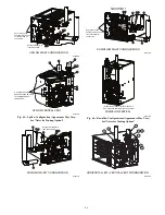
Page 45: ...the furnace vestibule could result in the circulation of carbon monoxide throughout the structure The vent pipe and combustion air pipe must be a continuous pipe while passing through the blower compa...

Page 46: ...ry See Notes for Venting Options 1 2 3 4 5 6 7 5 Rotate vent elbow to required position DOWNFLOW LEFT CONFIGURATION A11311A 1 2 3 4 5 6 7 5 Rotate vent elbow to required position Any other unused knoc...

Page 47: ...ION A11329A Fig 47 Horizontal Left Appearance May Vary See Notes for Venting Options ALTERNATE COMBUSTION AIR CONNECTIONS HORIZONTAL RIGHT VERTICAL VENT CONFIGURATION A11337 Requires Internal Vent Kit...

Page 48: ...tion air pipe adapter with gasket to furnace 7 Attach combustion air pipe to adapter with silicone Pilot drill a1 8 in hole in adapter and secure with a 7 x 1 2 in sheet metal screw Attach gaskets to...

Page 49: ...oncentric vent or by installing the required termination elbows as shown in Figs 56 57 and 58 For Ventilated Combustion Air Termination see Fig 59 5 Clean and dry all surfaces to be joined 6 Check dry...

Page 50: ...f the plastic vent adapter 8 Slide the adapter over the vent pipe and align the screw holes in the adapter with the dimples in the furnace casing 9 Pilot drill 1 8 in screw holes for the adapter in th...

Page 51: ...e 4 in diameter hole for 2 in kit or one 5 in diam eter hole for 3 in kit 2 Loosely assemble concentric vent combustion air termina tion components together using instructions in kit 3 Slide assembled...

Page 52: ...tion Pipe Dia mm 38 51 64 38 51 64 38 51 64 38 51 64 76 38 51 64 76 38 51 64 76 7 6 1 6 1 6 1 6 1 15 2 13 7 6 1 18 3 15 2 6 1 9 1 9 1 7 6 6 1 22 9 19 8 18 3 6 1 25 9 22 9 19 8 18 3 0 1 5 1 5 6 1 7 6 6...

Page 53: ...vailable through Replacement Components required under 10 ft 3 M TEVL in all orientations Required for installations from 0 2000 0 to 610 M above sea level Failure to use an outlet restric tor may res...

Page 54: ...h MEVL 95 ft 29 M For 2 pipe from Table 16 Is TEVL less than MEVL YES Therefore 2 pipe MAY be used Example 2 A direct vent 60 000 BTUH furnace installed at 2100 ft 640M Venting system includes FOR EAC...

Page 55: ...soffitt located above the vent termination within a horizontal distance of 2 ft 61 cm from the centerline of the vent termination 6 ft 2 M Clearance to a ventilation exhaust including HRV ERV on eithe...

Page 56: ...minimum of two sides beneath the floor See Note 4 Manufacturer s Recommendation See Notes 3 8 M Clearance to each side of the centerline extended above or below vent terminal of the furnace to a drye...

Page 57: ...lly open on a minimum of two sides beneath the floor See Note 4 Manufacturer s Recommendation See Notes 3 8 M Clearance to each side of the centerline extended above or below vent terminal of the furn...

Page 58: ...ver is greater Side wall termination with 2 elbows preferred 12 in min 305 mm from overhang or roof Maintain 12 in 305mm minimum clearance above highest anticipated snow level or grade whichever is gr...

Page 59: ...59 A13078 Fig 58 Alberta and Saskatchewan Vent Termination Fig 59 Vent Terminations for Ventilated Combustion Air...

Page 60: ...p switches that may be set to meet the application requirements Refer to the Adjustments section for setup switch configurations To set these setup switches for the appropriate requirement 1 Remove bl...

Page 61: ...operty damage personal injury or loss of life WARNING Adjustments FIRE HAZARD Failure to follow this warning could result in personal injury death and or property damage DO NOT bottom out gas valve re...

Page 62: ...sure of 4 5 in w c for natural gas The maximum inlet gas pressure is 13 6 in of water column If the inlet pressure is too low you will not be able to adjust the manifold pressure to obtain the proper...

Page 63: ...i Jumper R to W W1 and W2 This keeps furnace locked in high heat operation when both W W1 and W2 are ener gized j Repeat items d through g for high heat operation repeat ing Step 2 and adjusting the...

Page 64: ...y See Table 19 and Fig 40 65 and 73 Adjust Cooling Airflow High Speed and Low Speed Cooling The ECM blower can be adjusted for a range of airflows for low speed or high speed cooling See Table 9 Air D...

Page 65: ...rners will re light when furnace cools down 2 Check Pressure Switch es This control proves operation of the draft inducer blower a Turn off 115 v power to furnace b Disconnect inducer motor lead wires...

Page 66: ...66 A190070 Fig 64 Service Label Information...

Page 67: ...h Description 1 Default A C airflow when A C setup switches are in OFF position 2 Default Low Stage A C airflow when CF switches are in OFF position A190148 Fig 66 Airflow Selection based on 350 CFM T...

Page 68: ...69 138 346 13 277 555 1385 53 68 136 340 14 257 514 1286 54 67 133 333 15 240 480 1200 55 65 131 327 16 225 450 1125 56 64 129 321 17 212 424 1059 57 63 126 316 18 200 400 1000 58 62 124 310 19 189 3...

Page 69: ...5 44 3 6 1 5 44 3 7 1 6 43 3 4 1 4 43 3 5 1 5 4000 900 44 3 4 1 4 44 3 5 1 5 44 3 7 1 5 44 3 8 1 6 1219 925 44 3 2 1 4 44 3 4 1 4 44 3 5 1 5 44 3 6 1 5 950 45 3 7 1 6 44 3 2 1 3 44 3 3 1 4 44 3 4 1 4...

Page 70: ...can perform basic maintenance functions such as cleaning and replacing air filters All other operations must be performed by trained service personnel A qualified service person should inspect the fur...

Page 71: ...the number of long flashes For an explanation of status codes refer to service label located on blower door or Fig 64 and the troubleshooting guide which can be obtained from your distributor Retriev...

Page 72: ...rust corrosion soot or excessive dust If necessary have furnace and burner serviced by a qualified service agency 5 Inspect the vent pipe vent system before each heating sea son for water leakage sagg...

Page 73: ...Representative drawing only some models may vary in appearance A11584 Representative drawing of DIBC blower wheel only some models may vary in appearance A190094 Fig 67 Blower Assembly 5 Remove screws...

Page 74: ...tion Adjust temperature rise as shown in Adjustments Section Cleaning Burners and Flame Sensor The following items must be performed by a qualified service technician If the burners develop an accumul...

Page 75: ...wer on at external disconnect fuse or circuit break er 17 Run the furnace through two complete heating cycles to check for proper operation 18 Install control door when complete 2 1 2 in 64 4 1 1 4 in...

Page 76: ...w 4 Attach the relief hose to the relief port on the condensate trap and collector box 5 Secure tubing to prevent any sags or traps in the tubing 6 Connect condensate drain elbow or drain extension el...

Page 77: ...or loss of life WARNING 13 Replace main furnace door Secondary Heat Exchangers The condensing side inside of the secondary heat exchanger CANNOT be serviced or inspected without complete removal of th...

Page 78: ...re switch LPS fails to remain closed the inducer motor IDM will remain running at high speed After the low heat pressure switch re closes the furnace control CPU will be gin a 15 second prepurge perio...

Page 79: ...ened The outdoor unit will stop and the fur nace blower motor BLWM will continue operating at cool ing airflow for an additional 90 seconds Jumper Y Y2 to DHUM to reduce the cooling off delay to 5 sec...

Page 80: ...blower motor BLWM will switch to operate at low cooling airflow When the thermostat is satisfied the blower motor BLWM will operate an additional 90 seconds at low cooling air flow before transitioni...

Page 81: ...d G 24V thermostat signals Run system through a low heat high heat or cooling cycle to check operation Status codes are erased after 72 hours or can be manually erased by putting setup switch SW1 1 in...

Page 82: ...82 A190262 Troubleshooting Guide Continued...

Page 83: ...83 344605 2 REV C A190259 Fig 73 Wiring Diagram...

Page 84: ...act BRYANT HEATING COOLING SYSTEMS Consumer Relations Department P O Box 4952 Syracuse New York 13221 4952 1 800 428 4326 Have available the model number series number and serial number located on the...

Reviews: