77
ELECTRICAL SHOCK AND FIRE HAZARD
Failure to follow this warning could result in personal injury,
death, and/or property damage.
Turn off the gas and electrical supplies to the furnace and
install lockout tag before performing any maintenance or
service. Follow the operating instructions on the label
attached to the furnace.
!
WARNING
A11273
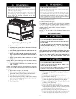
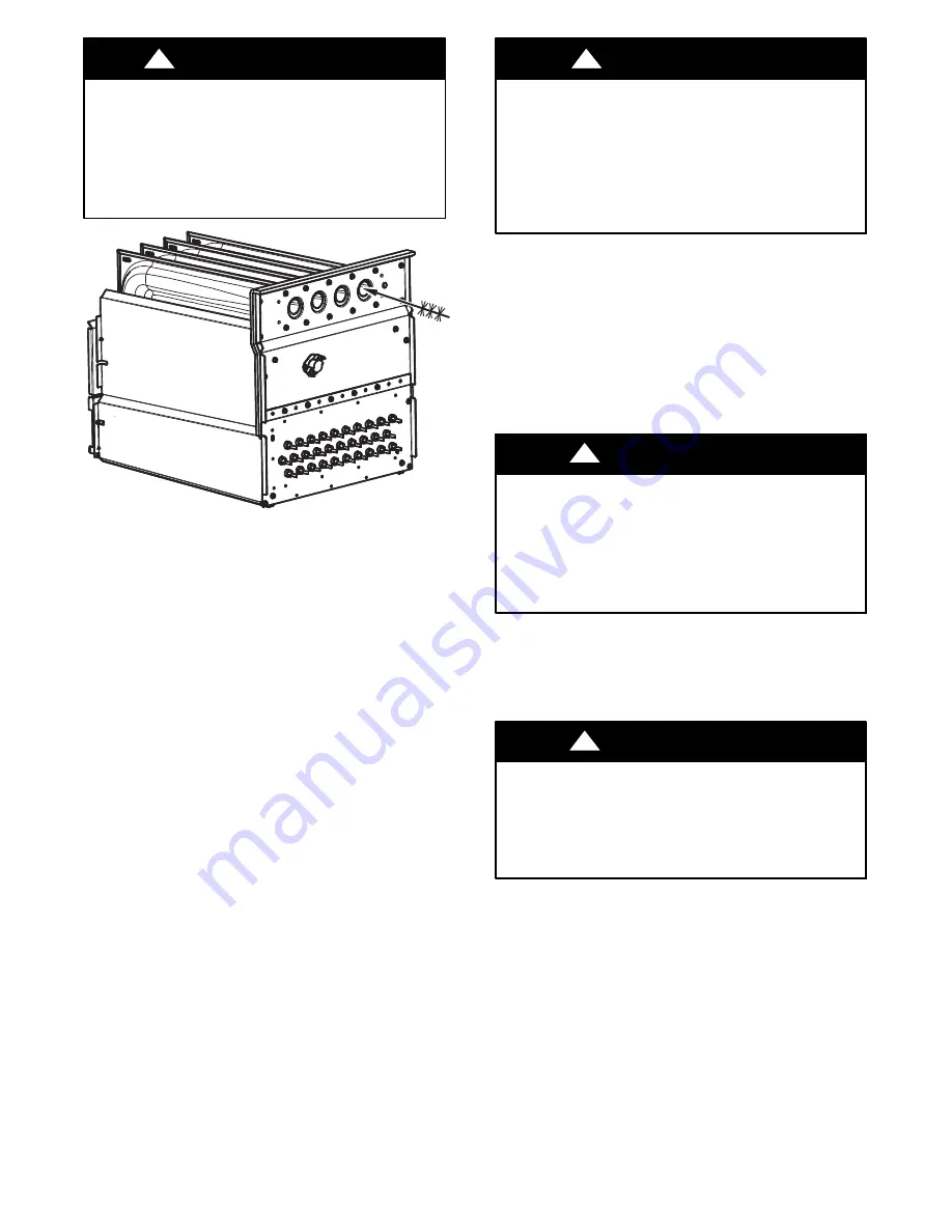
Fig. 71 -- Cleaning Heat Exchanger Cell
2. Remove control door.
3. Disconnect wires or connectors to flame rollout switch, gas
valve, igniter, and flame sensor.
4. Using backup wrench, disconnect gas supply pipe from fur-
nace gas control valve.
5. Remove two screws attaching top filler plate and rotate up-
wards to gain access to screws attaching burner assembly to
cell panel.
6. Remove screws attaching burner assembly to cell panel.
See
Fig.
68.
NOTE:
Burner cover, manifold, gas valve, and burner assembly
should be removed as one assembly.
7. Clean heat exchanger openings with a vacuum and a soft
brush. See
Fig.
71.
NOTE
: After cleaning, inspect the heat exchangers to ensure they
are free of all foreign objects that may restrict flow of combustion
products.
8. Reverse items 6 through 1 for reassembly.
9. Refer to furnace wiring diagram and reconnect wires to
flame rollout switch, gas valve, igniter, and flame sensor.
10. Turn on gas and electrical supplies to furnace.
11. Check furnace operation through 2 complete heat operating
cycles. Look at burners. Burner flames should be clear blue,
almost transparent. See
Fig.
62.
12. Check for gas leaks.
FIRE OR EXPLOSION HAZARD
Failure to follow this warning could result in personal injury
death, and/or property damage.
Never purge a gas line into a combustion chamber. Never test
for gas leaks with an open flame. Use a commercially available
soap solution made specifically for the detection of leaks to
check all connections. A fire or explosion may result causing
property damage, personal injury or loss of life.
!
WARNING
13. Replace main furnace door.
Secondary Heat Exchangers
The condensing side (inside) of the secondary heat exchanger
CANNOT be serviced or inspected without complete removal of
the heat exchanger assembly. Detailed information on heat
exchanger removal can be obtained from your Distributor.
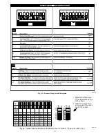
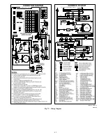
Wiring Diagrams
See
Fig.
73 for the Deluxe 4--Way Multipoise Furnace wiring
diagrams.
WINTERIZATION
UNIT AND PROPERTY DAMAGE HAZARD
Failure to follow this caution may result in unit component or
property damage.
If the furnace is installed in an unconditioned space where the
ambient temperatures may be 32
_
F (0
_
C) or lower, freeze
protection measures must be taken to prevent minor property
or product damage.
CAUTION
!
Since the furnace uses a condensing heat exchanger, some water
will accumulate in the unit as a result of the heat transfer process.
Therefore, once it has been operated, it cannot be turned off and
left off for an extended period of time when temperatures will
reach 32
_
F (0
_
C) or lower unless winterized. Follow these
procedures to winterize your furnace:
UNIT COMPONENT DAMAGE HAZARD
Failure to follow this caution may result in damage to the
furnace and other property damage.
Do not use ethylene glycol (automotive antifreeze coolant or
equivalent). Failure of plastic components may occur.
CAUTION
!
1. Obtain propylene glycol (RV/swimming pool antifreeze or
equivalent).
2. Turn off gas and electrical supplies to your furnace.
3. Remove furnace control door.
4. Remove the top unused rubber plug from the port on the
collector box opposite the condensate trap. See
Fig.
60.
5. Connect a field supplied 3/8--in. (9.5--mm) ID tube to the
open port on the collector box
6. Insert a field supplied funnel into the tube.
7. Pour 1 quart of anti--freeze solution into the funnel/tube.
Antifreeze should run through the inducer housing, overfill
condensate trap and flow to an open drain.
8. Replace the rubber plug in the port on the collector box.
9. Remove the middle unused rubber plug from the port on the
collector box opposite the condensate trap. See Fig. 60.


